BenB
|
| posted on 3/1/08 at 12:08 PM |

|
|
Any metallurgy experts out there (re welding)
Well after much f'ing around, Fed(up)ex finally got my crank pulley to me. I would post a picture of shiny Honda goodness but my digicam has
gone walk-abouts!
For the EFi / alternator / supercharger / dry sump installation I need to add a little spacer cotton reel ] [ shape device which the secondary pulley
can sit on top off. I need the spacer device to allow the secondary pulley to clear the clutch housing. Considering I'll be putting about 30Bhp
through the secondary pulley, the spacer needs to be quite strongly attached to the crank pulley (the pulley wheel has mahusive teeth on it so
there's no chance of it slipping on the crank). The only problem is how do I attach the spacer to the crank wheel? I was considering drilling
some holes through it and bolting but now I've got the pulley I see its quite small and there's not really enough meat on it to drill
securing holes (though I might change my mind yet).... Now I'm thinking more along the lines of sparky blue glue (welding).
Presumably the suitability, type and ease of welding will depend upon the metal the pulley is made out of... How easy / hard / impossible is it to
tell what metal something is made from? Presumably a quick check with a magnet will tell me if its ferous. Then what? Check the density of it and
compare to known ferrous / non-ferrous materials??? How do I tell if it's cast or forged? I'm thinking if it's cast iron I'm a
bit buggered....
Obviously I don't want the spacer to shear. A sudden lack of boost, oil pressure and ignition timing info from the trigger wheel would probably
be "bad".
Cheers (as ever) for any info!!!
|
|
|
|
|
Howlor
|
| posted on 3/1/08 at 12:42 PM |
|
|
Do you have some pics of the two pulleys so we can see the problem.
thanks,
Steve
|
|
|
Mr Whippy
|
| posted on 3/1/08 at 12:44 PM |
|
|
if it's a cast pulley you'll probably see rough cast areas on the back. It's not going to be a forging, waste of time for a pulley
or alloy (think you would have noticed that). Leaving only the question - cast iron or steel, my bet would be steel.
Try welding a bead on the face if it bubbles and looks like it's eaten away the surface then it's cast iron. You can still weld cast iron,
though if you heat it up till almost red, then it just welds like steel.
[Edited on 3/1/08 by Mr Whippy]
|
|
|
BenB
|
| posted on 3/1/08 at 12:58 PM |
|
|
Whahay! Found the digicam... Here's what it looks like. Much more shiney in real life!!!
 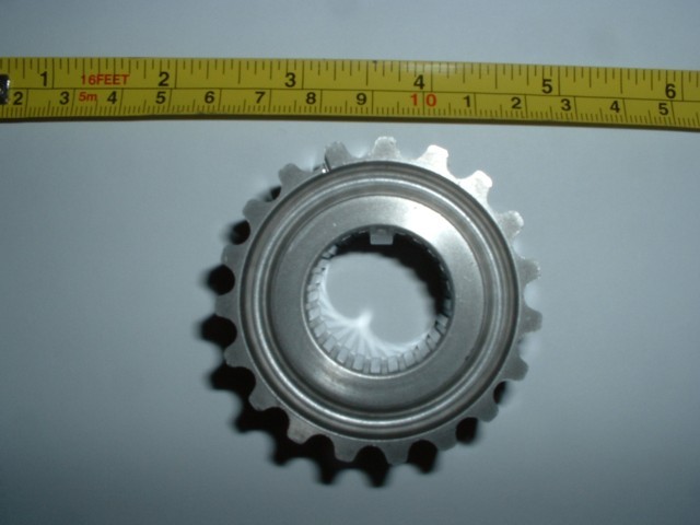
ST1100 pulley wheel
 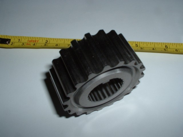
ST1100 pulley wheel
|
|
|
omega 24 v6
|
| posted on 3/1/08 at 01:06 PM |
|
|
I'd hazard a guess at it being steel. However you also need to take into account that it may or may not have been heat treated?? with the
splines and the toothed belt it PROBABLY has to some extent. If so a rub with a file might tell you i.e. if it skids over it it's probably been
heat treated and welding could affect this process.
If it looks wrong it probably is wrong.
|
|
|
Howlor
|
| posted on 3/1/08 at 01:16 PM |
|
|
Do you only need the external teeth? If so cant you have a local engineering company make you an adaptor that will fit into the inner splines and
connect onto the pully?
Or just get a company to make you it all in one piece. May be the best option in the long run.
Steve
|
|
|
BenB
|
| posted on 3/1/08 at 01:24 PM |
|
|
No can do unfortunately- I need the internal and external teeth because this is the crank pulley (IE still needs the internal teeth to hold it on the
crankshaft) and it'll still be cranking the timing belt via the outer teeth. The pulley at the other end of the spacer is easy cos it's
very big so I can drill some bolt holes in it around the edge and bolt it to the flat end of the ] [ shape spacer.... It's at the crank end
I'm struggling!!
Actually, getting a custom made one made may be option. The only issue would be that the teeth profile needs to be spot on else it'll eat the
timing belt with obvious effects!!!
[Edited on 3/1/08 by BenB]
|
|
|
02GF74
|
| posted on 3/1/08 at 01:34 PM |
|
|
not sure I follow what you are doing but I take it you cannot make a keyway in the shaft to hold the pulley in place?
I am guessing not since the shaft is too short.
A possible alternative would be to make small holes in both and keep them together with hardened steel pins - but dunno how you would top the pulley
coming away from the gear.
|
|
|
Mr Whippy
|
| posted on 3/1/08 at 01:47 PM |
|
|
I have to say I'm getting a bad feeling about this, things are going to snap...
That little thing is just to small to muck around with, it's nothing like doing this on a car engine.
Take a picture to show the clearance issue you have with the clutch and the belt, perhaps that can be resolved rather than go this route.
|
|
|
tomblyth
|
| posted on 3/1/08 at 01:55 PM |
|
|
Id drill and tap it 5x8mm holes on equidistant PDC and fit High tensile steel cap screws, Its probably only case hard so you may have to grind the
front off first ! use a mild steel spacer the crank pulley will most likley be EN34 or similar
|
|
|
BenB
|
| posted on 3/1/08 at 02:05 PM |
|
|
Okay, here's a dodgey diagram 
 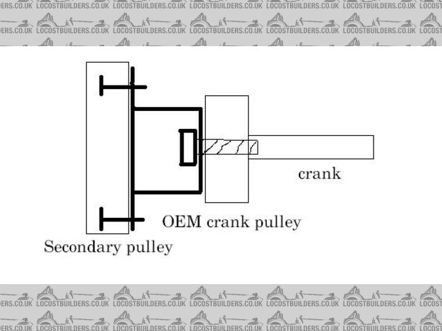
pulley wheel diagram
The crank pulley has got a keyway (and splines) to keep it on the crank. There's a bolt at the end that keeps it held onto the crank.
The secondary pulley is a multi-V ribbed belt that is going to drive the dry-sump pump, the alternator (the bike one is pants) and the blower.
The bit drawn in thicker black is the top-hat type spacer device. The crank pulley is well held onto the crank and the secondary pulley will be bolted
to the outer end of the spacer. The problem is how to secure the spacer to the crank pulley.
There's only about 11mm of metal between the inner splines and the outer teeth. I'd be wary of drilling too far into that- after all, 5mm
bolts would only leave 3mm of metal either side of the bolt..... I could use pins but even if you had quite a few I expect they're shear when
they had 30Bhp put through them.....
I suppose I *could* share the splines on the crank shaft IE get this cog and lathe a recess on the end of it so the outer teeth are still there but
the splines are only present for the inner 50%. Then get the spacer made that has inner teeth to fit the splines and keyway on the crank and yet fits
within the newly made recess in the crank pulley.... With a bit of skill I could make the OD of the spacer the same as the ID of the recess in the
crank pulley.... Put the spacer in the freezer to shrink it and voila...... Perhaps!!!
There's no way I can run all the stuff I need to off the crank pulley without adding the secondary pulley and even if I didn't have a spacer
I'd still need some way of connecting the crank and secondary pulleys...
|
|
|
russbost
|
| posted on 3/1/08 at 02:11 PM |
|
|
From the pics it's steel, most likely case hardened to the outer teeth. I would have said you'd be quite safe welding to it - wrap a wet
rag around the outer teeth to prevent damage to the heat treat & cool regularly in oil (beware it's known to burst into flames ) before the
heat has a chance to transfer too far. ) before the
heat has a chance to transfer too far.
Edited to say, having seen your diagram I would keep the distance between the end of the crank & the secondary pulley as short as possible to
reduce the potential bending moment.
[Edited on 3/1/08 by russbost]
I no longer run Furore Products or Furore Cars Ltd, but would still highly recommend them for Acewell dashes, projector headlights, dominator
headlights, indicators, mirrors etc, best prices in the UK! Take a look at http://www.furoreproducts.co.uk/ or find more parts on Ebay, user names
furoreltd & furoreproducts, discounts available for LCB users.
Don't forget Stainless Steel Braided brake hoses, made to your exact requirements in any of around 16 colours.
http://shop.ebay.co.uk/furoreproducts/m.html?_dmd=1&_ipg=50&_sop=12&_rdc=1
|
NOTE:This user is registered as a LocostBuilders trader and may offer commercial services to other users
|
BenB
|
| posted on 3/1/08 at 02:12 PM |
|
|
I suppose going down the bolt route it should be possible to work out what shear forces I'm going to be applying to the bolts... though quite
how I get from 30Bhp to a shear value I'm not so sure
|
|
|
BenB
|
| posted on 3/1/08 at 02:15 PM |
|
|
Oh yes- I'm keeping the spacer as short as possible. Should be less than 15mm
|
|
|
russbost
|
| posted on 3/1/08 at 02:17 PM |
|
|
Quick "idiot check" on that shear value - a Kart rear axle has about 20 bhp going thro' it, the rear wheels & slicks are
attached with 3 x 6mm threaded bolts. You have some horrendous shock loads & bending moments on a kart rear wheel in addition to the 20bhp power
transmission & I've never seen one shear the bolts.
I no longer run Furore Products or Furore Cars Ltd, but would still highly recommend them for Acewell dashes, projector headlights, dominator
headlights, indicators, mirrors etc, best prices in the UK! Take a look at http://www.furoreproducts.co.uk/ or find more parts on Ebay, user names
furoreltd & furoreproducts, discounts available for LCB users.
Don't forget Stainless Steel Braided brake hoses, made to your exact requirements in any of around 16 colours.
http://shop.ebay.co.uk/furoreproducts/m.html?_dmd=1&_ipg=50&_sop=12&_rdc=1
|
NOTE:This user is registered as a LocostBuilders trader and may offer commercial services to other users
|
BenB
|
| posted on 3/1/08 at 02:19 PM |
|
|
Nice thinking! That sounds possible then!!
|
|
|
BenB
|
| posted on 3/1/08 at 02:57 PM |
|
|
Right, I reckon that should do it. I'll machine out the curved recess in the face of the pulley to make it square (with rounded edges to prevent
stress raisers) then machine the front of the spacer into a ring that sits in the recess. Then drill 4* holes @ constant PCD (5 or 6mm) and tape the
ones in the pulley. Jobs a good'un.... I'll get drawing up a picture on Emachineshop to illustrate the plan!!! If I keep on shearing the
hi-spec bolts I'll weld it as well!!!!
|
|
|
omega 24 v6
|
| posted on 3/1/08 at 03:27 PM |
|
|
Mmm I'd be worried that yournot thinking abot the weekest link in all this THE MULTI VEE belt. I'm no expert but to think about driving an
alternator supercharger and drysump may be asking to much from one LONG belt. the amount of drag on the belt MAY lead to premature stretching and
slipage IMHO Also have you thought about the large pulley having a geared effect on the smaller dry sump and alternator pulleys. Apologies if
I'm teaching you to suck eggs but it'd be better to think about it all now.
If it looks wrong it probably is wrong.
|
|
|
gazza285
|
| posted on 3/1/08 at 03:38 PM |
|
|
Which way is the crank turning? Would the pulley be turning clockwise or anticlockwise as you look at it? If it is anticlockwise then you can weld the
bolt into the spacer/pulley carrier and your drive and mounting problems are solved in one. If it's clockwise, then the bolt would just come
undone . .
DO NOT PUT ON KNOB OR BOLLOCKS!
|
|
|
BenB
|
| posted on 3/1/08 at 05:04 PM |
|
|
quote:
Originally posted by omega 24 v6
Mmm I'd be worried that yournot thinking abot the weekest link in all this THE MULTI VEE belt. I'm no expert but to think about driving an
alternator supercharger and drysump may be asking to much from one LONG belt. the amount of drag on the belt MAY lead to premature stretching and
slipage IMHO Also have you thought about the large pulley having a geared effect on the smaller dry sump and alternator pulleys. Apologies if
I'm teaching you to suck eggs but it'd be better to think about it all now.
No problems re checking the obvious- I make very stupid mistakes sometimes!! I've chosen then secondary pulley diameter so that it spins up the
alternator pulley at the right speed. The Supercharger it'll spin at the correct speed for about 6PSI of boost which is all I'm going for
to begin with. Then I'll get a smaller one made up to spin it faster when I want to run higher boost levels...
|
|
|
BenB
|
| posted on 3/1/08 at 05:21 PM |
|
|
quote:
Originally posted by gazza285
Which way is the crank turning? Would the pulley be turning clockwise or anticlockwise as you look at it? If it is anticlockwise then you can weld the
bolt into the spacer/pulley carrier and your drive and mounting problems are solved in one. If it's clockwise, then the bolt would just come
undone.
Good plan!! I'll have a look tonight. I knew at one point (cos I worked out where the blower needs to sit by knowing the rotation of the crank)
but I've obviously forgotten!!
|
|
|
chriscook
|
| posted on 3/1/08 at 08:01 PM |
|
|
If you are using a bolted joint then the bolts should not be in shear themselves. The friction between the surfaces held together by the bolts should
be transferring the torque.
|
|
|
dmac
|
| posted on 3/1/08 at 08:30 PM |
|
|
Why not drill plain holes for dowels instead of bolts and then use an extended crankshaft bolt (with a large washer to stop the dowels coming out) to
hold the top hat spacer and crankshaft pulley in place?
Duncan
|
|
|
BenB
|
| posted on 3/1/08 at 10:22 PM |
|
|
I just worry still about the dowels being in shear.... I suppose it's true that when it's all bolted up the friction should partially hold
things in place.... Dilemas..... 
Thanks for all the options everyone!! My respects to the Locostbuilders thinktank
|
|
|