
Level of accuracy needed for bellhousing/adaptor fabrication?
interestedparty - 2/11/10 at 09:37 PM
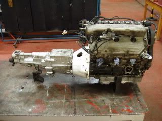
I'm contemplating fitting a different gearbox to an engine (make doesn't matter) and I already have the engine, the bellhousing and the
original gearbox, which is not suitable.
So, what I am wondering about it using the existing bellhousing as a pattern for a new one, but with a different gearbox mounting pattern.
The problem is how accurate would I need to be in measuring all the parts concerned? If the accuracy needed is outside of what can be done with care
and hand tools, is there another way?
Or, if I was able to obtain another bellhousing, one that matched the new gearbox, could the old and new BH be combined and if so how would the
respective position of each part best be found?
BTW, I've already checked to see if there is a ready made product answering my requirements, and there isn't.
Danozeman - 2/11/10 at 09:43 PM
It needs to be very accurate with respect the input shaft being where it needs to be for the clutch. If its not central it wont fit and would shake
itselft to bits if you did get it together.
NS Dev - 2/11/10 at 09:46 PM
as a stab in the right direction, I would not want much more than 6 thou misalignment. You would probably just about get away with 8 thou
interestedparty - 2/11/10 at 09:47 PM
quote:
Originally posted by Danozeman
It needs to be very accurate with respect the input shaft being where it needs to be for the clutch. If its not central it wont fit and would shake
itselft to bits if you did get it together.
Indeed, that was exactly what I was thinking, but in engineering there is always a tolerance, even if it is a very small one. I need to know whether I
can get that close or whether there are other ways of achieving it
nick205 - 2/11/10 at 10:00 PM
Aside from casting a new bell housing I would guess the best way is to have an adapter plate made using laser or water jet profiling. I guess then
the trick is to accurately transfer the existing block and bell housing pattern into a single set of dimensions...?
interestedparty - 2/11/10 at 10:08 PM
How about this?
I work out how long the BH needs to be in total. I cut the front half of the engine BH to a fraction short of half that length, mill it parallel to
the enigne mounting face, then cut the back half of the gearbox BH and mill the same way. Then I fit each BH half to its respective component, then
offer the gearbox up to the engine so that the input shaft engages the clutch and crank spigot.
So, with the gearbox now centralised to the engine, weld the two BH halves together. Any thoughts on that idea?
clairetoo - 2/11/10 at 10:28 PM
To test that method without cutting anything up , just grab the gearbox input shaft and see how much you can move it - I'm betting on at least a
couple of mm's 
I made my first one by hand , and made a mistake in the positioning which put the gearbox nearly 2mm below centre - and after only a year the clutch
plate got a bit rattly ! (and that was the only problem , nothing actually failed)
It would be nice to be able to get it within a few thousands of an inch - but unless it's going to be completly CNC'd that just aint gonna
happen - although the only bits that need to be accurate are the dowel holes to both the engine and gearbox .
SPYDER - 2/11/10 at 10:46 PM
Hi there.
As clairetoo has said I wouldn't trust the input shaft to align properly. It's bound to have a bit of wobble in it.
What about making a a dummy shaft that accurately slides inside the thrust bearing tube. You'll need to have the gearbox fitted to do this.
Machine the end of this shaft to fit into the end of the crank.
This ought to give better alignment than using an input shaft.
As regards welding the two parts together I would try and fit several dowels through the joint otherwise the parts will distort.
It might be worth welding a few inches then letting the assembly cool down.You could check alignment between each weld session.
Does this make any sense?
Geoff
clairetoo - 2/11/10 at 10:51 PM
One possible problem with the cut and weld idea - are both bellhousings the same shape ?
Cuz if they are not , you may find filling a 30mm miss-match with weld a bit of a mission
owelly - 3/11/10 at 12:07 AM
I made my own bellhousing. It was more accurate than the original Alfa casting. I used the locating dowels as datum points, along with the centre line
of the crank and the input shaft. It never jumped out of gear which is the main problem with misaligned input shafts, and worked a treat!
NS Dev - 3/11/10 at 10:32 AM
this is the thing, it all depends on what gearbox etc you are using.
I refrained from going into detail as there's lots of it!
Basically, if you possibly, in any way at all, can use a ballhousing that fits the ENGINE, then do that, then modify the other end to suit the
gearbox.
not always possible as often the bellhousing that fits the engine may be too long for the chosen gearbox input shaft.
However, if its not, then a lot of gearboxes (such as the ford type 9) have a nice machined concentric regsiter on the front, which, using a turned
adaptor machined to suit, can be used to locate your bellhousing and give you a reference point.
You certainly can't just use the input shaft etc, as most still move even when locked into 4th gear!
Duncan Mould - 3/11/10 at 06:45 PM
I recently did this with a rover V8 block I put in a 944. used the original bell housing from the V8 then took the bellhousing from the 944 then
placed the V8 bell house on a flat plate bolted an angle grinder with a skinny disk about 10mm from the top, turned it on and whilst my mate
controlled the angle grinder moved the bell house around (this ensured my locost level cut). Did the oppisite with the 944 housing and mated the 2
together. I was able to allign the two tack with weld and later fully weld after checking with a DTI and all is well. The Rover V8 by the way has now
got 2 cosworth cylinder heads and turbo's strapped to it and is running 8 second 1/4's on the drag strip.