will121
|
| posted on 14/11/09 at 07:48 PM |

|
|
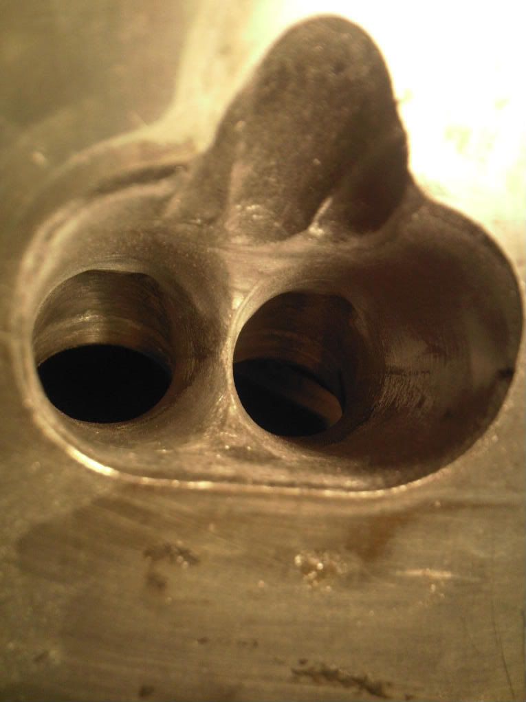
just made/bodged a flow bench and zetec ported head
just made today a very basic flow bench to see if my home porting zetec cylinder head works at all.
tested the pressure drop difference between the bare ported and un-ported cylinder and seemed to show a improvement. Very basic principal I know and
removed the filters from the Dyson to get more suck.
With a bit of maths inlet up 5.5% improvement exhaust up 4.3%
its all been worth the hours in the cold porting
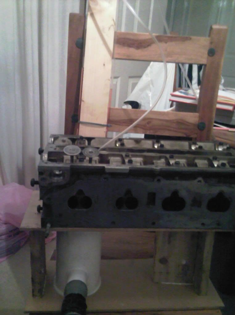
and just in case you were wondering. yes it is in my dining room and surprising im happily divorced
i did take a video but for some reason lost it, will try again later.
|
|
|
|
|
MikeR
|
| posted on 14/11/09 at 08:01 PM |
|
|
joys of car building in your own house .... amazingly always seems to include not having a woman in the house 
|
|
|
MikeR
|
| posted on 14/11/09 at 09:43 PM |
|
|
g/f just made me point out - she slept with some wheel arches the other night.
Bit worrying as i thought she slept with me and the rear arches just happened to be in the room 
|
|
|
will121
|
| posted on 14/11/09 at 09:53 PM |
|
|
quote:
Originally posted by MikeR
g/f just made me point out - she slept with some wheel arches the other night.
Bit worrying as i thought she slept with me and the rear arches just happened to be in the room
car parts in the dining room is one thing, but getting them in the bed room is taking it to another level!!!
|
|
|
MikeRJ
|
| posted on 14/11/09 at 11:01 PM |
|
|
You should have the valves fitted to measure flow, they can make a big difference to the effective shape of the port.
How are you measuring airflow, orifice plate and manometer? Often thought a MAF sensor would be simple enough to set up for this.
|
|
|
will121
|
| posted on 15/11/09 at 12:41 PM |
|
|
quote:
Originally posted by MikeRJ
You should have the valves fitted to measure flow, they can make a big difference to the effective shape of the port.
How are you measuring airflow, orifice plate and manometer? Often thought a MAF sensor would be simple enough to set up for this.
im not measuring actual flow improvements as not got a orifice plate, all ive measure is that the gas flowed cylinder has a lower vacuum formed within
it compared to the standard cylinder hence a less of a restriction to air flow/more flowing.
This was a first attempt on a bare head, will do it again with valves fitted to be more representative but will need a taller manometer first.
|
|
|
ncoll
|
| posted on 15/11/09 at 02:51 PM |
|
|
quote:
How are you measuring airflow, orifice plate and manometer?
Why would you want an orifice plate, with a simple flowbench like this?
ncoll
|
|
|
MikeRJ
|
| posted on 15/11/09 at 04:07 PM |
|
|
quote:
Originally posted by ncoll
quote:
How are you measuring airflow, orifice plate and manometer?
Why would you want an orifice plate, with a simple flowbench like this?
ncoll
Because measuring only pressure drop across the port doesn't give you an airflow measurement. You can get a relative measurement if you can
guarantee airflow hasn't changed between successive readings, but that's very unlikely.
Essentially to get a measure of how well something flows, you need the pressure drop at a known airflow (or vice versa). Knowing something gives a
certain pressure drop at an unknown airflow is of little use by itself.
[Edited on 15/11/09 by MikeRJ]
|
|
|
ncoll
|
| posted on 15/11/09 at 05:55 PM |
|
|
I suppose if you made several different size orifice plates and calculated the flow of each plate, you could calibrate it in some sort of fashion. But
i would assume that this flowbench has been built just to see what difference a bit of simple porting would make. The problem with most home made
flowbenches is that they measure air leakes more than they measure flow through the port. The number of photos iv'e seen on forums of
flowbenches, not one has had the cylinder head clamped to the bench. The pipe joints are taped up with gaffer tape, they then make them selves a
helgensen calibration plate and come up with flow figures that put to shame figures of people who have been flowbench developing heads for many years.
The DIY flowbench is fine for the purpose it was made for, it is not however a reliable tool to compare figures from a genuine flowbench used
properly.
ncoll
|
|
|
will121
|
| posted on 15/11/09 at 06:08 PM |
|
|
the idea was to make something very basic and hopefully to show to myself that the 10hours to be spent in the cold garage porting the head had some
potential benefit, i didnt want to compare mine to a profesionally done head on a actual flow rate. Head wasnt clamped to bench, worse than that it
was sat on a thin ring of blue tac to seal it!!
|
|
|
ncoll
|
| posted on 15/11/09 at 06:25 PM |
|
|
Don't get me wrong, i'm all for people building this type of flowbench, and keep up the good work. You would probably be better making a
rubber gasket up instead of using blutac, plus you will have to test for leaks with all valves shut without sucking all your water out of your
manometer. You could make some calibration plates up to help to see what your heads are flowing, a standard zetec head flows about 110 cfm at
10" test pressure. If you made a calibration plate that flows that type of air you could mark that on your manometer. A modified silvertop zetec
flows around 135 cfm at 10" test pressure at 1/2" valve lift. e-mail me if you want the formula for calculating airflow through a sharp
edged orifice (hole).
Happy Grinding
ncoll
|
|
|