Hudsonn
|
| posted on 13/9/15 at 06:44 PM |

|
|
Yamaha R1 Breather mods - Can someone explain my current set up?
Hi all,
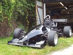
I've just signed up to the forum after a couple of months browsing. I've recently bought an MK Indy R1, 4 laps round Curborough and it
threw a rod out the side of the block! Sticking with the onwards and upward spirit, I've put another 5VY R1 engine in and have another spare 5VY
in the garage to build up incase this one goes bang as well!
As far as I can see from the wreckage a big end bolt has let go. Based on a little research it looks like this kind of incident is fairly common and
can be solved by various oil supply and breather mods. The problem is, I have very little technical knowledge in order to carry out the mods which
I'm hoping is where you guys can help!
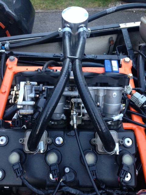
Currently I have a baffle plate in the sump and a catch can attached as per the below pictures (all this was in place when I bought the car).
Can someone please explain what the catch can is actually doing? i.e. the hose on the right of pic 1 is doing what, and taking oil where, and why
etc..?! My current set up In lemans terms: the 2 cam cover breathers are going straight in to the catch can, another hose is going from the catch can
to the gearbox, and the large diameter pipe from the bottom of the can is going to atmosphere (its not attached at the other end anywhere). Is this
correct or should it be different?

From what I've seen I need to drill a couple of different holes in the top of the cam cover and blank of the current ones? Why is this different
to the holes that are currently there? I'm confused on why that one makes a difference!
Beyond those simple points, I'm going to be using this entirely as a track car so I guess an accusump and oil coiler will be necessary?
Any explanation of other mods I should be carrying out or things I should change in the current set up much appreciated!
![]()
|
|
|
|
|
daniel mason
|
| posted on 13/9/15 at 06:59 PM |
|
|
Adithorpe will help out with all things r1
|
|
|
Hudsonn
|
| posted on 13/9/15 at 07:25 PM |
|
|
I shall await his arrival!
Just so people know, I have read the in depth thread about R1 breather mods  I'm just still a touch confused about how my current set up
relates to the info in that thread! I'm just still a touch confused about how my current set up
relates to the info in that thread!
|
|
|
adithorp
|
| posted on 13/9/15 at 08:25 PM |
|
|
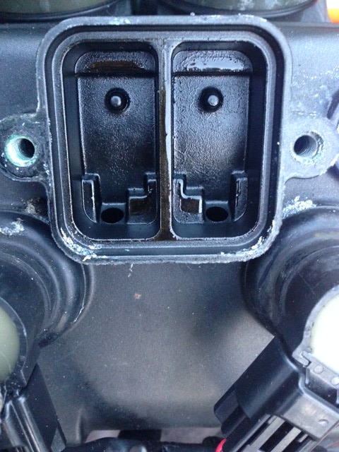
Well... what you've got isn't right and you're right you need to mod' the AIS housings in the cam cover as you've read.
Currently it's venting and excess oil/fumes into the exhaust via the AIS porting.
The issue with the R1 is the gearbox breather is the only one and under left hand corners the oil can swill up higher than the breather, then the
crankcase compression pushes the oil up the tube and if in it's original configuration into the throttles... not good!
You need to (with cover removed) the block the two holes/ports to the exhaust (@bottom in the pic) in each housing with grub screws/taper plugs/etc.
Then drill 2 holes though to the cam box, near the lower edge when fitted (so oil can drain back in) then refit the caps (outlets to the top side when
fitted). I put some folded mesh inside to condense oil vapour on.
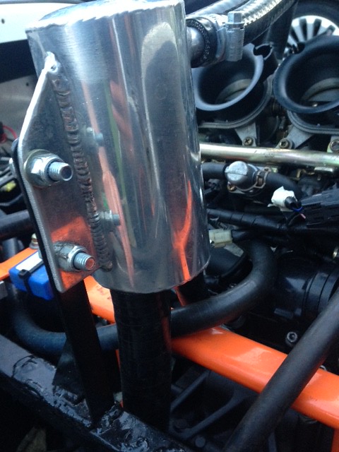
Then run pipes from there and the gearbox breather pipe to a your catch tank. You need a breather on the catch tank either to atmosphere or fed into
the air box.
Using the tank you have, I'd put the breather on one of the top outlets. Connect the 3 vents together and into the other top outlet. Then block
the bottom one in some way, preferably with some way of opening it to drain the tank. The tank shouldn't collect much if any oil but it will
collect some water condensation if you do short runs especially in cold conditions.
"A witty saying proves nothing" Voltaire
http://jpsc.org.uk/forum/
|
|
|
Hudsonn
|
| posted on 13/9/15 at 09:32 PM |
|
|
quote:
Originally posted by adithorp
Well... what you've got isn't right and you're right you need to mod' the AIS housings in the cam cover as you've read.
Currently it's venting and excess oil/fumes into the exhaust via the AIS porting.
The issue with the R1 is the gearbox breather is the only one and under left hand corners the oil can swill up higher than the breather, then the
crankcase compression pushes the oil up the tube and if in it's original configuration into the throttles... not good!
You need to (with cover removed) the block the two holes/ports to the exhaust (@bottom in the pic) in each housing with grub screws/taper plugs/etc.
Then drill 2 holes though to the cam box, near the lower edge when fitted (so oil can drain back in) then refit the caps (outlets to the top side when
fitted). I put some folded mesh inside to condense oil vapour on.
Then run pipes from there and the gearbox breather pipe to a your catch tank. You need a breather on the catch tank either to atmosphere or fed into
the air box.
Using the tank you have, I'd put the breather on one of the top outlets. Connect the 3 vents together and into the other top outlet. Then block
the bottom one in some way, preferably with some way of opening it to drain the tank. The tank shouldn't collect much if any oil but it will
collect some water condensation if you do short runs especially in cold conditions.
Cheers, I think I get you. The tank I have has 4 outlets though, so could I run the gearbox breather to one towards the bottom of the tank (where it
is at the moment), the 2 crank case breathers connected together to one of the top 2 outlets, blank the bottom one as you suggest then leave the other
top one open to atmosphere?
So when this set up is done properly, is the idea that if the oil level swills above the gearbox breather the oil gets routed in to the catch can
rather than the throttles? But then what are the crank case breathers connected to the catch can for? Surely they could just vent to atmosphere?
Forgive me if I'm being stupid here, I'd just like to try and understand what everything is actually doing!
|
|
|
adithorp
|
| posted on 13/9/15 at 09:58 PM |
|
|
Sorry didn't see the second outlet on the bottom. No idea where that is going from the pictures. I'd guess at it just drains under the car
somewhere; Tracks won't be happy if that's the case and I'd guess you're losing a lot of oil that way. That might be why you
got to the point of oil starvation and threw a rod.
If the oil does swill above the gearbox outlet then the gas can still vent from the cam case... so not forcing the oil further up the gearbox vent
pipe and it just runs back once out of the corner. If you just vent the cam cover ones to atmos' then the vent will get very oily and make a
mess. By taking it to a tank you catch any oil/liquid in the tank and vent just the crankcase gas. I wouldn't use the bottom outlet for the
gearbox pipe as anything that does come through the breathers will drain back into the gearbox; As all I get actually in the tank is oily water from
condensation I wouldn't want that going back in.
With a baffle, the breather mod and the correct oil level you shouldn't have any issue. Oil level 2/3 to 3/4 way up the sight glass (engine hot
and running) is what works. An oil cooler is an option but I ran a standard 5vy for 6 years without with no problem; Only when I went to a tuned
ex-race motor did I need to fit one.
"A witty saying proves nothing" Voltaire
http://jpsc.org.uk/forum/
|
|
|
Hudsonn
|
| posted on 13/9/15 at 10:08 PM |
|
|
I did some more research, could someone just confirm I've got this right please....
High crankcase pressure can cause an engine to spit it's oil out of the breather, not enough oil and things go bang?
To alleviate the crankcase pressure people are drilling 2 more holes (breathers) in the cam cover, it just so happen that the easiest place to put
these is in the AIS system because the connected for hoses are already there?
And the AIS exhaust ports are blocked off just because they aren't needed? <---- thats the bit I don't get still, why they need
to be blanked off?
Edit: just saw your reply, all makes sense! I'll have a re-jig and post some pics of a correct set up.
[Edited on 13/9/15 by Hudsonn]
[Edited on 14/9/15 by Hudsonn]
|
|
|
CosKev3
|
| posted on 14/9/15 at 09:54 AM |
|
|
Out of interest how do the bottom holes connect to the exhaust ports?
Another thing to note if it's just normal silicone pipe that's been used the oil will start to break down the pipe,it could be a concern
on the pipe from your gearbox to catch tank as when parts of the pipe start to break up it will drop down into your crankcase.
Standard silicone pipe is only for air or water,you need flurosilicone lined silicone pipe for oil or fuels.
|
|
|
adithorp
|
| posted on 14/9/15 at 12:30 PM |
|
|
quote:
Originally posted by CosKev3
Out of interest how do the bottom holes connect to the exhaust ports?
Theres galleries through the cover and side of the head. Normally there's a plate inside the covers with reed valves and the top outlets connect
to the air-box via an ECU controled solenoid. Allows aditional air through into the exhaust to improve emmisions... plays havoc with trying to get
through IVA car type emmisions though.
"A witty saying proves nothing" Voltaire
http://jpsc.org.uk/forum/
|
|
|
CosKev3
|
| posted on 14/9/15 at 12:49 PM |
|
|
quote:
Originally posted by adithorp
quote:
Originally posted by CosKev3
Out of interest how do the bottom holes connect to the exhaust ports?
Theres galleries through the cover and side of the head. Normally there's a plate inside the covers with reed valves and the top outlets connect
to the air-box via an ECU controled solenoid. Allows aditional air through into the exhaust to improve emmisions... plays havoc with trying to get
through IVA car type emmisions though.
Ah right cheers.
|
|
|