
what's wrong with it?
giel - 20/2/04 at 09:42 PM
Hi everyone
I've been busy setting up a front suspension for the last weeks, I'd appreciate it if some of you want too take a glance at it and give
comments.
It's got full camber compensation, almost no track change because of the low RC, and the RC hardly moves up or down at 2 degrees. All looks very
good so far.
The only things that I'm concerned about, are the lateral movement of the RC (50 mm @ 2°) and the relative short SAL. Also the A-arms are very
inclined compared to other designs.
Most cars seem to have longer SAL and lateral RC movement is supposed to be a bad thing, but why??? Am I missing something?
BTW: the upper and lower A-arms are represented as the lines between the nodes, with the dimensions 275 and 380 attached.
[Edited on 20/2/04 by giel]
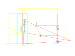
Rescued attachment susp3.gif
Hellfire - 20/2/04 at 09:49 PM
MY EYES! WHAT HAPPENED TO MY EYES???
Better colours would be appreciated...
(what's happened to my eyes?)
giel - 20/2/04 at 10:10 PM
sorry, this should be better...
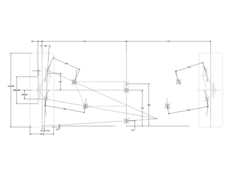
Rescued attachment susp5.gif
rontyler - 20/2/04 at 10:17 PM
How does it look in bump and roll?
GTAddict - 20/2/04 at 10:26 PM
A 225mm wide tyre that's 700mm in diameter? To me, that's about 100mm too large.
This wouldn't matter, but it will affect the way you see your ground clearance - you'll think you've got 50mm more than you have.

To get some idea of good dimensions for your tyres, look at Toyo UK's excellent
website of Proxes T1-S sizes.
This may make you re-evaluate how much angle you have on your lower wishbone... not that I'm saying you're wrong... 
Mark.
giel - 20/2/04 at 10:34 PM
quote:
Originally posted by rontyler
How does it look in bump and roll?
I haven't checked bump+roll yet, just wanted to see if I'm on the right track. I do wonder why everybody always looks at the 1" bump +
2° roll situation.
to Mark: I know the tyre dimension isn't realistic, but I overlooked the fact that it's affecting my geometry. Good one, thanks. I'll
correct it.
any other comments, anyone?
rontyler - 20/2/04 at 10:42 PM
"I haven't checked bump+roll yet, just wanted to see if I'm on the right track."
Can't really say without at LEAST bump and roll.
I do wonder why everybody always looks at the 1" bump + 2° roll situation.
"
Partly becuase it looks like there would be significant scrub... and bump/roll will show it. Also it can show where the RC goes, swing arm length
changes, camber curves, etc.
pbura - 20/2/04 at 11:51 PM
quote:
Originally posted by giel
I do wonder why everybody always looks at the 1" bump + 2° roll situation.
Allan Staniforth used 1" bump + 2° roll as an acid test for evaluating a suspension with his "string computer", probably the biggest
reason.
Giel, I had a brainwave once, that if you assume an SAL and a roll center from the outset, all you then have to do is to find a spot for the upper
inboard pivot that keeps the RC steady.
Crappy drawing and explanation on my webpage 
I also referred to a free suspension proggie that you can use to test out your setup:
http://www.racetechmag.com
It's wishbone.exe from the Downloads section, and you'll need Microsoft QuickBasic to run it.
In reality, one could avoid my drawing exercise practically altogether by plotting the lower chassis pivot, then 'fishing' with Wishbone for
the upper.
Hope this helps!
Pete
P.S. I have had no luck ever getting anyone else to try this, but it completely demystified wishbone suspensions for me
ProjectLMP - 21/2/04 at 03:10 AM
I am certainly no expert in this area but this is what I do know. Generally you have two conflicting requirements with the suspension geometry.
Firstly, you want to keep the loaded wheel vertical (or even with some negative camber) when cornering i.e. the chassis is rolling. Secondly you want
to keep both wheels vertical when the suspension goes into bump. For the front suspension this assists under braking and for the rear under
acceleration. The problem is that the two requirements conflict with each other. Looking at your setup it looks like it will be good in the roll
situation but not so good under bump. F1 type suspensions with long swing axles optimize camber in bump at the expense of roll. However, they
don't roll much anyway so its less of an issue.
One reason the combined bump/roll situation is analysed is because this is the attitude a car takes when a car enters a corner following a brake zone
(when driven hard on the track)
Another important point to keep in mind regarding camber compenstation is that different tires have different requirements. Some like a more negative
camber (Radials) and some don't need as much (Bias-ply). Also the shape of the tire also effects this. Generally, tires with rounded edges
require more negative camber than ones with square edges. Take a look at the difference in static negative camber a Michelin F1 tire has vs a
Bridgestone.
I think the reason the lateral rollcentre location should not move too much is that it changes the degree to which the chassis will roll. Take as an
extreme case where the rollcentre is located right where the loaded tire is. In this case there would be a higher roll resistance than if it was
located at the centre of the car. So if the rollcentre moves all over the place the car may not feel progressive when cornering.
End of my ramblings. Just for info:
For my front suspension from 0 to 1 degree of roll:
Rollcenter height changes by 0.040"
Rollcenter moves 3.8"
Track changes 0.002"
Maximum positive camber (assuming 0 static camber) is 0.75 degrees.
[Edited on 21/2/04 by ProjectLMP]
cymtriks - 21/2/04 at 11:34 PM
I think that what you are missing may be that the contact patch has low stability in bump. A long SAL trades roll stability for bump stability. Making
an estimate based on camber change in bump the Elise has SALs of about 170 inches at the front and about 115 inches at the rear. From memory this is
close to a suggestion given in the Costin and Phips chassis book
[Edited on 21/2/04 by cymtriks]
Spyderman - 22/2/04 at 05:05 PM
Your setup can only ever give negative camber on bump and droop. Assuming wheel is setup with no camber at static.
The traditional method of having the lower wishbone level or slightly downhill from chassis is to optimise the camber change when cornering. As your
lower arm can only move outward as it moves down it is giving negative camber to the inside wheel when you ideally need positive.
Also, having the roll centres so low gives more roll leverage. Keeping the roll centres nearer to the COG will help reduce roll.
Terry
kb58 - 22/2/04 at 05:43 PM
quote:
Originally posted by Spyderman...Also, having the roll centres so low gives more roll leverage. Keeping the roll centres nearer to the
COG will help reduce roll.Terry
It's all a trade off. If you put the roll center the car won't roll at all! A good thing? Well, no, because you then have no way to tune
the suspension. If the car never leans, changing sway bars, springs, and shocks won't have any effect...
You need the car to lean some... which argues for placing the RC below the CG by "some amount."
rontyler - 22/2/04 at 06:31 PM
...and, if memory serves, high RC's made Ralph Nader famous ;-)
cymtriks - 22/2/04 at 10:05 PM
Just for your interest
Elise RCs
front 30mm
rear 75mm
Experimental independent rear Caterham7 RCs
front 30 mm
rear 65 mm
I have done some analysis of suspension geometry and some odd effects appear with very low RCs and high roll. This might explain why even F1 cars
rarely go below 20mm at the front even with virtually zero roll and suspension movement.
giel - 22/2/04 at 10:08 PM
Thanks people, your replies have pointed some things out for me that I'll have to work on. Who said it was going to be easy, right?
Before I return to the CAD system, some remarks to a few of you:
Ron: "Partly becuase it looks like there would be significant scrub...".
There's actually very little scrub, at least up to 2° roll. I believe there will never be much scrub as long as the RC is low.
Pete: " if you assume an SAL and a roll center from the outset, all you then have to do is to find a spot for the upper inboard pivot that keeps
the RC steady "
I think I understand your method, but how do you, at the same time, keep your camber the way you want it?
ProjectLMP: "I think the reason the lateral rollcentre location should not move too much is that it changes the degree to which the chassis will
roll. Take as an extreme case where the rollcentre is located right where the loaded tire is. In this case there would be a higher roll resistance
than if it was located at the centre of the car. So if the rollcentre moves all over the place the car may not feel progressive when cornering. "
I don't understand. How does the roll resistance get higher when the roll centre moves to the side? And would you say that your 3.8" is a
low or high migration?
Syderman: " Your setup can only ever give negative camber on bump and droop. Assuming wheel is setup with no camber at static. "
I don't agree. As long as my IC is on the inside, the wheel will go in positive camber on droop. The CAD model showed full camber compensation on
the inner as well as the outer wheel.
Anyway, it's clear to me that I'll need a compromise between cornering- and braking grip. Although a mid-engined car brakes a lot on the
rear axle too, it's something to consider. I'll get back to work and let you know what comes out. Maybe I'll start with the rear
suspension first, it might be a bit easier.
GTAddict - 22/2/04 at 10:33 PM
If you compress the suspension while also in roll, then you might have a problem with inner wheel camber. This probably isn't a worry for you
with the front - braking heavily under cornering isn't the best way to drive a mid-engined car if you want to stay facing the right way.
quote:
Originally posted by giel
Maybe I'll start with the rear suspension first, it might be a bit easier.
However a similar design for the rear might be trickier if the inner goes into severe negative camber under acceleration. If you don't have an
LSD, you'll risk spinning away power as you go away from the apex.
This is why Mallock always stuck to his solid rear axle.  An old article about linkages for solid rear
axles here, in case you're going that way.
An old article about linkages for solid rear
axles here, in case you're going that way.
Mark.
pbura - 23/2/04 at 02:09 AM
quote:
Originally posted by giel
Pete: " if you assume an SAL and a roll center from the outset, all you then have to do is to find a spot for the upper inboard pivot that keeps
the RC steady "
I think I understand your method, but how do you, at the same time, keep your camber the way you want it?
It's a bit hard to tell on my drawing, but I actually drew three wheels: (1) static, (2) inboard wheel where I wanted it (no camber change) at
1" bump + 2° roll, and (3) outboard wheel (also where I wanted it with a -1° camber change) at 1" bump + 2° roll.
Note that I didn't get what I wanted in the unloaded wheel. This was physically impossible, so I went for correct camber on the loaded wheel.
I'll confess cheating a bit, because I first drew up a book Locost suspension and found that it had an 80" SAL, so I used that. This fell
into the low end of the moderate range as opined by Allan Staniforth in his 'Race and Rally Car Source Book'.
My desired outcomes for camber change were also heavily influence by data in the Staniforth book.
I strongly recommend the (free) Wishbone program I mentioned, or the also free) Suspen program available at
http://users.erols.com/smitch/Suspen/. That way, you can step your design through bump and/or roll cycles to see how it behaves. I like
the layout of the Wishbone program myself, though you have to monkey around with steering pivot locations a bit to negate bump steer.
You'll find that short SALs give good camber control in roll, but suffer in bump, and vice versa for long SALs. Roll center locations are also
more sensitive with long SALs.
The whole process really is the epitome of compromise.
I suggest that you design the front first, because it's the hardest to get right. Then for the rear you can just raise the RC a bit.
One more subject you might want to think over is that of weight transfer, as alluded to by Messrs. ProjectLMP and kb58. Ideally, IMO, with typical
Locost springing, you would want to limit roll to about 2° in a 1G turn. If you don't want to use anti-roll bars, this will determine where your
RC needs to be.
Some mind-expanding/blowing material here:
http://www.smithees-racetech.com.au/

Pete
kb58 - 23/2/04 at 03:39 AM
Keep in mind that after you've analyzed this to death, figured out EXACTLY where the pickup points must go, that you'll be lucky if
they're within 1/16" of the target... and 1/8" movement during welding is extremely common.
In otherwords, don't kill yourself trying to make it perfect, there is not such thing.
Tudor (Ted) Miron - 23/2/04 at 01:22 PM
Hello Giel,
There are many good suggestions in this topic. I’ll try and take it more practical and add some of my thoughts.
First it would be very helpful if you give dimensions of your suspension in X, Y, Z - X (for- aft) measured from axle line (we don’t care about X for
now), Y (width) as dimensions from car centerline and Z (vertical) measured from ground plane. Obviously we need lower and upper arms inner and outer
pickup pints. Also we need track width and tire diameter. Than I’ll be happy to check it out and may be give some suggestions.
Assuming your choice of RC height = 50mm. First we want RC to move about the same as CG in bump i.e. chassis is lower 1” than RC is lower by as close
to 1” as possible.
Than we want RC to stay stable vertically in roll and than stable laterally in roll.
Now why we do bother about RC migration? First is because certain amount of sprung lateral weight transfer (WTrc) is via RC: WTrc = RCHeight: Track.
Main thing is Roll moment arm – distance between RC and CG. As this is impossible (and undesirable) to keep RC height constant with sprung mass
moving up and down it’s possible and desirable to keep this moment arm constant or closely so as this will have major effect on axle roll resistance
and dynamic weight transfer. This is why lateral RC migration can be important – if it moves considerable amount towards inner tire than moment arm
length changes increasing roll resistance and WT at this axle. This is used widely in oval track racing as major tuning tool.
If it all was so simple than our life would be much easier yet not that interesting. So once again why we do bother about RC migration and its
influence on WT? It’s because it influence the loads and forces acting on tire contact patch – the only thing that really matters. Tire is VERY load
sensitive device i.e. amount of lateral force that tire delivers vary largely with load (as well as many other things). When cornering reaction force
at the tire acts through RC. If RC is not exactly on ground plane this force will have two components vertical and lateral. In case of higher than
ground RC vertical component is “jacking” sprung mass – famous jacking effect.
(This is actually more complicated as in true forces are acting through instant centers and may be different at inner and outer wheel) This jacking
effect may have MAJOR effect on tire loads – usually bad. Explanation is long but late studies showed that its effects are not VERY significant with
relatively low RC – 2” or less. If resources are not of same level as Williams F1 and we can’t make infinite amount of simulations and on track
testing it is usually desirable to have relatively low RC so to minimize jacking effects. F1’s are playing some very strange games with RC – like
having it VERY high with huge jacking forces - they use it to support stable aero platform – very complicated and hard to get right. I prefer
slightly lower than ground front RC and little higher than ground rear. This is an easy way to get in Ball Park. Easy to set up and not very front
ride height sensitive.
Ted
pbura - 24/2/04 at 07:38 PM
quote:
Originally posted by Tudor (Ted) Miron
I prefer slightly lower than ground front RC and little higher than ground rear. This is an easy way to get in Ball Park. Easy to set up and not very
front ride height sensitive.
Ted, out of curiosity, are you going to use anti-roll bars front and rear with that setup?
I'm also curious as to how your design's going. Please ramble on at will or set up a new topic of you like
Pete
Tudor (Ted) Miron - 24/2/04 at 08:36 PM
Hi Pete,
Yes I'm going to use ARB's front and rear. With all their shortcomings they ARE very valuable tuning tools - first of all fast and easy. In
single seater (and sports racer could be considered a close brother) it's common to give 40% and more of total roll resistance to ARB's.
Lower than ground front RC requires much stronger ARB but well known CART engineer says that thinking of it as a handicap is wrong.
I know one VERY succesful race car with - 0.7" front RC and NO ARB!
Also in last 4 -5 years wheel rates raised massively - at list in higher echelons of racing. This became possible as dampers internal friction was
decriesed very significantly. You'll be surprised how "soft" are current state of the art dampers (Ohlins, Penske)
Design is going nicely - Suspension modelling is done for now... I'm burried in CFD atm. It will be a true tunnel car - not a conventional flat
bottom with diffusers. It seems that full length tunnels give much less pitch/rideheight/roll sensitive results. As I planned car has 2 configurations
build in. 4" ride height for street use and 2" for track use. Well there are actually 3 configs. When go from track trim to road trim
and not changing arms pickup points I get 1" front and allmost 3" rear RC. Still one has to change rack location (4 bolts) and pushrod to
bellcrank - 4 more bolts (2F, 2R) Changing this will change motion ratio from 1.15 to 0.75 which changes wheel rate allmost twice.
If one is not lasy he should proseed to change lower arm outer point and upper arms inner points and get allmost same geometry as in race config. So
there's virtually 3 cars in one. I should also mention that in race trim there is some serious downforce - requiring for much higher wheel rates
than road trim.
Sorry for messing this thread
Ted
PS: As usually - sorry for my English
Tudor (Ted) Miron - 24/2/04 at 08:42 PM
Hey Pete - just saw you're mantioning Dale Thompsons web site - he's a nice guy
Ted
rontyler - 24/2/04 at 09:03 PM
"Now why we do bother about RC migration? First is because certain amount of sprung lateral weight transfer (WTrc) is via RC"
Ted,
I've always understood the implied importance of a stable RC. What I don't get is that, traditionally speeking, damaper rates differ
dramatically with respect to rebound to compression ratio. My point? How can the geometric RC be followed when there is such a wide variance in
"wheel rate" (side to side)? In other words, during a transitional manuever, it seems that the geometric RC would have pretty minimal
influence due to the rebound rate on the inside wheel being significant and the outboard compression rate being minimal (relatively speaking). Can you
"set me straight" on my thinking?
TIA
pbura - 24/2/04 at 10:14 PM
quote:
Originally posted by Tudor (Ted) Miron
Hey Pete - just saw you're mantioning Dale Thompsons web site - he's a nice guy
The Smithees site? Well, I can believe that he is, as he's put a lot of valuable stuff on his page for free. He seems to have a first-class
operation.
Thanks for the update on your project. Sounds like you're learning a lot and really going for something innovative and seriously competitive.
All the best,
Pete
Tudor (Ted) Miron - 24/2/04 at 10:33 PM
Ron,
First I have to say that I'm not an "expert" - all I'm saying is not nessecerally right. Lets take a simplifyed transitional
manuver car turning at decreasing radius corner at constant speed. Let's assume that at begining it wasn't cornering at max speed and with
less radius it does reach max cornering limit. While roll angle is increasing dampers add their share to dynamic WT distribution. But we should look
at car as pair of roll couples - front and rear - differense in WT distribution between F and R axles influense it's behavoir. So it's not
really matters if Rebound and bump stiffnes is different because they both work on same roll couple. Also to my understanding dampers mostly determine
not how much weight is trnsfered but how fast it is transfered. Another thing is in racing we don't usually see that big difference in bump and
rebound forces as in "normal" street car.
I'd say that here's is another reason for low RC - we may like to minimise "geometric" WT and maximise it's part that is
going through springs and bars.
Hope I didn't confuse it further
Sertanly my "English" doesn't help.
Ted
[Edited on 24/2/04 by Tudor (Ted) Miron]
Tudor (Ted) Miron - 25/2/04 at 10:01 AM
Ron,
I thought that I have to add some complication to this . In reality car DOESN'T roll around it's geometric RC. There's
"true" force based RC - which is usually little higher than pure geometric.
Ted
rontyler - 25/2/04 at 03:22 PM
Ted,
In your first reply... “Another thing is in racing we don't usually see that big difference in bump and rebound forces as in
"normal" street car.”
This is about the only thing that I feel addresses the question. However, I can’t help feeling that there’s “more”
Then you post...
“In reality car DOESN'T roll around it's geometric RC. There's "true" force based RC - which is usually little higher than
pure geometric.
Now this has my attention. Please share with us what you know or point us to a book or example. Question... what did you mean by “higher than
geometric”? The force is higher or the location is higher?
Thanks for you time.
Tudor (Ted) Miron - 25/2/04 at 04:17 PM
Ron,
I thought that first part of my post was addressing your question. It doesn't really matter is there big difference in rebound/bump shock forces
or not. Point is that part of WT is via springs, bars and DAMPERS and part is via RC. RC part may change significantly in transient if RC is messing
around. It may cause the car to change it's attitude from understeer to oversteer - there and back during one turn and even one phase of turn.
There are also jacking forces generated straight through A arms from instant centers. I was suggested to think about those jacking as same as anti -
dive but lateraly.
This forces may have significant effect on CG height, roll (and bump sifness during turn - loaded wheel) stiffness and ultimately tire loading.
Here's a copy of letter from one VERY well educated person:
"I would like to respond to the many discussion points on the subject of roll center & RC migration. Sorry to be so long winded but this is
a complex subject.
I have spent many years working within Ford Racing to study NASCAR, Indy Car & sports car suspension geometry & the associated effects. This
has included design, modeling & testing both on the track & in laboratories. Within Ford Motor Co. we have laboratories that can actually
measure the forced based effects of roll center height & RC migration to a very accurate degree.
Here are a few interesting points:
1. Suspension models in general are not forced based but are relatively simple geometric models.
2. Geometric models are very good for defining the basic character of rigid suspensions (heims etc. no rubber bushings). These include camber gains
both jounce & roll. Roll center placement & migration, roll rates, steering geometry etc.
3. Geometric lateral roll center migration, in general, increases as the geometric roll center gets closer to the ground.
4. Geometric roll centers are an approximation of the real world of forced based roll centers. (what happens on the race track & how the vehicle
transfers weight from tire to tire)
5. Forced based roll centers can be modeled in ADAMS or other such complex models.
6. Force based effects can be measured in the laboratory very effectively.
7. Force based roll centers can & do migrate & this can have a very significant effect on weight transfer, jacking forces & the resulting
COG height and tire contact patch loads.
8. Vehicles with relatively high roll centers (2" - 3" or more above ground statically).
In forced based testing those vehicles that exhibit significant geometric RC migration, have higher tire contact patch weight transfer than do
vehicles with the same roll center height & little or no lateral roll center migration
9. Vehicles with low roll centers (very near the ground).
In forced based testing these vehicles do not have siginificant weight tranfer associated with roll center height & or roll center migration.
10. The forced based roll center is always higher than the geometry indicates. (for all vehicles we have tested)
11. Many NASCAR suspension geometries have roll centers that migrate (geometrically) this results in greater force based weight transfer & a
resulting reduction of grip at the limit.
in summary:
1. Very few of us have the ability to conduct forced based modeling or testing.
2. Use geometric models to define your basic geometry requirements.
3. Do your best to reduce geometric lateral migration of the roll center without compromizing the important parameters.
4. If your roll center is very close to the ground lateral migration of the RC is MUCH LESS important than with higher roll centers. To say this the
other way; cars with higher roll centers should have MUCH less lateral roll center migration.
Again sorry to be so long winded & I hope that I have not confused the issue.
Jay Novak
Also found this paper: http://www.ee.ic.ac.uk/CAP/Reports/2001/ASCInteractions.pdf
Also I can recomend a new book " Introduction to race car engineering" - great stuff!
I have access to ADAMS/Car but currently I don't do much with it - it's VERY complicated ( at list for a such dumb guy like I am) - how
ever after aerodinamic study of my project will get more or less clear I'll come back to it and hope to finally learn how to get real profit
(not money ) out of this great tool.
Thank you
Ted
PS: Here's another informative words from another VERY good engineer " The biggest problem with above ground front RCs is the attendant
jacking effect. While it will cause quicker front transfer reactions, it also makes the front very sensative to ride height changes, and can cause the
car balance to change dynamicaly a LOT during cornering. As a consequence, it is a lot harder to get a good setup that is stable, predictable, and
doesn't eat front tires if things are off just a tiny bit.
A below ground front RC does require a much larger front roll bar than an above ground RC, but the thought that that is a handicap is a fallacy. Below
ground RC's actually transfer weight to the inside tire for a instant upon initial turn-in, which can dramatically help turn-in response. Also,
the lack of jacking effect makes the front VERY stable, especially in high speed corners and over undulations, as changes in ride height don't
upset the roll couple balance as much as an above ground RC. Trail braking is also enhanced because of that stability.
Softer compounds can also be used without killing them immediately, but the decrease in geometric transfer does make it harder to get heat into the
tires initially. Higher spring rates can be utilised to control aero stability without abusing the tires - assuming the shocks are set up correctly,
of course. "
And another one from him: " Obviously, the F1 guys have data resources that we can only dream about. All we can do is to first get a thorough
understanding of the way the forces work, and then spend a ton of time and money experimenting. I wish I had the resources and didn't have to
worry about next month's rent payments!
Sorry, but there is no such thing as a car that will lean into the turn with the CG above ground, the RC at a reasonable height above (or below),
and "conventional" suspension. Physics doesn't work that way! Even the old Bugs and Triumphs showed normal roll to the outside as they
jacked way up onto the outside tire.
However, that said, it IS possible to "trick" the roll to going negative thru some fancy and complicated linkages - it's been done in
the past. Of course, it can also be done thru active hydraulic rams in place of the shocks and springs or as a moveable pickup point for the
coilovers.
The problem with all of this is that almost no matter what you do, the "stiffening" in roll from the jacking forces also affects the bump
stiffness while cornering, at least that of the outside tire. But, this is also part of the reason that they can hit the curbs so hard without tossing
the car into the infield (along with possibly accelleration sensative shock valving).
There are aero reasons for sure in just about everything the F1 guys do suspension-wise nowadays - keeping a stable aero platform is the holy grail to
them."
Sorry for such a long post.
[Edited on 25/2/04 by Tudor (Ted) Miron]
[Edited on 25/2/04 by Tudor (Ted) Miron]
[Edited on 25/2/04 by Tudor (Ted) Miron]
rontyler - 25/2/04 at 04:35 PM
Ted,
Good stuff... Thanks!
So, it appears that the forces that "roll" a car about its RC, percentage-wise, are MUCH higher than any differences in wheel rates...
Agreed?
Thanks Again.
Alan B - 25/2/04 at 05:08 PM
quote:
Originally posted by Syd Bridge
.......But we're supposed to be building replicas of a '50s sportscars, aren't we??........
Not in this part of the forum Syd.......however your points are well taken...
I'm off...this thread is severely hurting my brain...
rontyler - 25/2/04 at 05:31 PM
"There was a discussion on this rollcentre thing a while back"
I'm unable to find it
"The major dynamic in cornering is the force of the CoM..."
CoM ????
Thanks.
Tudor (Ted) Miron - 25/2/04 at 06:05 PM
If you can't beat 'em with science, baffle 'em with bullsh1t! (Syd Bridge)
Thank you Syd
There was a discussion on this rollcentre thing a while back. Search it out and see what a couple of well known designers said about it in a
discussion I was privileged to be party to. (Syd Bridge)
Would you please post a link?
As for F1 and GT's.. Aerodynamics is the ONLY consideration. They must keep even flow over the wings. A car moving up and down detaches flow.
(Syd Bridge)
This IS very interesting “ detaches flow when moving up and down” - that’s what I call “science “
Therefore, suspensions are pegged to stop any droop at all, and bump is no more than 20-30mm. With so little movement, there is little need for any
fancy RC claptrap, and indeed, no way to design it in. (Syd Bridge)
F1 designer Steve Nichols was interviewed and he was asked how critical suspension geometry is these days. 'Not absolutely critical - not like
there is a vast amount of time to be had in it' was his reply. Of course, he was fired a few months later.
Why do you think they now run such extreme cambers? (Syd Bridge)
I thought that it’s some how mysteriously related with radial tire camber sensitivity – Oh sorry for starting ballsh1ting again
Because the suspension can't move to compensate in cornering. Go back a few years, and have a look at the suspension geometry. You'll find
things very different. The rear suspensions today, show more than a passing resemblance to those of a few years back, and for good reason. (Syd
Bridge)
The major dynamic in cornering is the force of the CoM acting against the contact patch. From there on, gravity takes over, and the suspension
geometry moves. (Syd Bridge)
– This is again very interesting – suspension moves because of gravity!
Keep to the basics and you can't go wrong. Keep CoM as low as possible, and configure the suspension arms to keep the contact patch as stable as
is possible. (Syd Bridge)
Good point – seriously
The rest is theoretical (and some practical) fertiliser. (Syd Bridge)
True in a sense that keeping the basics right is important. Main thing to keep in mind is to try and don’t SCREW anything badly. How ever I’d like
keep my right to try and learn what’s really happening.
Then there's driver preference and 'feel' to build in....... (Syd Bridge)
But we're supposed to be building replicas of a '50s sportscars, aren't we??(Syd Bridge)
Are we really?
Here I have to apologize for bollsh1ting people and promise to stop doing this – sorry.
Ted
Tudor (Ted) Miron - 25/2/04 at 06:07 PM
CoM = center of mass
rontyler - 25/2/04 at 06:14 PM
It seems that several "languages" are bieng used... CoM=CoG?
flak monkey - 25/2/04 at 06:19 PM
CoM and CoG are essentially both the same thing....but centroid is not....
CoM / CoG are the important ones though, both are where all the weight of the object, in this case the car, seems to act as a point mass. Which is
very useful when modelling things...but im sure you all know that anyway so now i will be quiet
Cheers
David
[Edited on 25/2/04 by flak monkey]
pbura - 25/2/04 at 06:37 PM
quote:
Originally posted by Syd Bridge
But we're supposed to be building replicas of a '50s sportscars, aren't we??
Dunno about you, Syd, but I'm building a Supercar... :O 
Fast, supple, and handling like an extension of my own body! Err, maybe better!
Kidding aside, I'd appreciate a link to that thread you mentioned, as I didn't have any luck searching.
I agree with you that, for the home builder who does not have access to a cyclotron for testing, the tried and true is the best way to success. I
also have tremendous respect for the Seven design as having brilliant suspension geometry. Before computers, even!
However, anti-roll bars are legitimate modifications to the original design, IMO, unless the builder is seeking authenticity (an honorable goal, btw).
The Seven relies on firm springing at the front and a high roll center at the rear to limit body roll, both of which become negotiable once ARBs
enter the picture.
Oh, yeah, we're talking about middies, aren't we? Well, in that case, ANYTHING goes! As far as Mr. Novak's opinions go, I
have seen his postings in another forum, and I would put my money on his knowing his hockey, and that his assertions would be worth investigating
further. His advice for the home designer is very sensible.
I also respect Ted for reasoning out his design process. I'm sure that when he's done, he'll have a good foundation for his decisions
and not just someone's say-so.
Pete
rontyler - 25/2/04 at 06:51 PM
"As this subject strays into areas where I derive some of my income, we'll leave it be."
I can respect that.
"Just stop looking for a problem and answer where they don't exist in the first place."
Can you REALLY say this in good conscience? From my point of view, this thread has turned into an attempt at understanding how the suspension
design effects weight transfer... in my experience, this is one of the more important aspects of vehicle handling. I don't see it as
dissmissable.
giel - 25/2/04 at 09:23 PM
it seems like I have stirred up some things with my question, never expected it to unleash such a load of knowledge!!
Anyway, I'll keep following what comes up on this subject, also in other threads and forums.
If anything, the comments in this thread have brought me to the decision to keep the front RC low with little migration vertical and lateral, and add
a ARB if necessary. Although some of you have given some reasons to use a long SAL, I keep having the feeling that the camber compensating effect of a
short SAL is very beneficial, despite of the undesired camber change in bump (can be reduced with anti-dive geometry!) .
I will keep the SAL fairly short until I have proof that it should be lengtened, not too late until it's welded together, right?
BTW I like these threads with some theoretical depth, better than just building by the book without knowing why.
Alan B - 25/2/04 at 09:43 PM
quote:
Originally posted by giel.........BTW I like these threads with some theoretical depth, better than just building by the book without
knowing why.
Good job too...it's all we have in the absence of one single definitive book on middy building....maybe it's because we ARE on our own to
certain degree that it is so appealing........who knows..
rontyler - 25/2/04 at 10:32 PM
quote:
Originally posted by giel.........BTW I like these threads with some theoretical depth, better than just building by the book without
knowing why.
Giel,
Sorry to have ransacked your thread... it does illustrate the diversity in suspension thinking... whats important to one person is drivel to
another and yet they can both be right! Keep us posted on your progress.

