
FEA results on my chassis...
Liam - 22/10/06 at 03:17 PM
Hello...
Been meaning to do it for ages, but have now finally FEA'd my chassis design. Am most pleased with the results, and if nothing else they show
how good the balsa wood model method is if you don't have access to FEA software (though everyone does cos it's free!), because that's
what i used to design and optimise it in the first place.
I'm using Grape, a free FEA tool that as far as i can tell can't model stressed panels - just the tubes. So my models are under-stiff as
they have no panels. I also only have a tube defenition for 1.5mm wall RHS instead of 1.6mm 16swg. With these limitations the Book chassis comes in
at just over 800 ft lb per degree as opposed to the known 1200 or so it is with panels and 16swg.
I was pleased then that my chassis comes in at 4500 ft lb per degree with no panels  . And amazed to find out how effective the removable
over-the-engine-bay brace is! My engine is wide and mounted far back so I can't have either R tube in the engine bay. This is why i went for a
structural scuttle and the removable brace (see photo archive). Without the brace fitted the stiffness is only about 1500 ft lb per degree! So that
few kgs of structure trebbles the chassis stiffness by itself! Even with two R tubes (purely hypothetical in my case as they wont fit) my chassis is
only 2400 ft lb per degree without the removable frame.
. And amazed to find out how effective the removable
over-the-engine-bay brace is! My engine is wide and mounted far back so I can't have either R tube in the engine bay. This is why i went for a
structural scuttle and the removable brace (see photo archive). Without the brace fitted the stiffness is only about 1500 ft lb per degree! So that
few kgs of structure trebbles the chassis stiffness by itself! Even with two R tubes (purely hypothetical in my case as they wont fit) my chassis is
only 2400 ft lb per degree without the removable frame.
Another significant point is the 'knee bars' that i've fitted from the outside of the cabin by your knees (where it starts to taper
inwards) diagonally forwards to the middle of the inside of the footwell (see photo archive). When I was balsa modelling and fitted the engine bay
frame the whole chassis became stiff apart from this kink in the chassis. I could see the sides flexing out significantly here on the balsa model so
i fitted the 'knee bars' which stopped it. Sure enough the FEA shows that those two tubes alone add 800 ft lb per degree by themselves!
It's worth pointing out though that without the engine bay frame fitted the chassis' wobbliness is irredeemable and these knee bars only add
about 20 ft lb per degree - so only worth adding on a stiff chassis.
Well just wanted to share that! With the panelling i'll be up around 5000 ft lb per degree which aint bad for an open roofed steel tube frame.
And all this achieved with some simple balsa wood modelling - only verified by FEA. So have a go if you're doing something a bit different to
the book and want to optimise your chassis (although that said, the FEA is actually less time consuming and less messy :p).
Liam
greggors84 - 22/10/06 at 03:26 PM
Got any FEA images? Would be interested to see them.
Liam - 22/10/06 at 03:32 PM
Was gonna post one - but any biew i choose just looks like a mess of lines - so probably of little use 
will see whta i can do though
Winston Todge - 22/10/06 at 03:37 PM
That's certainly one hell of a project build you've got there! Looking proper sweet bud!
Chris.
Liam - 22/10/06 at 04:02 PM
Well there you go - showing stress and 50x displacement...
Liam

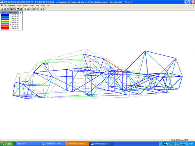
Rescued attachment FEA.jpg
liam.mccaffrey - 23/10/06 at 12:13 PM
thats really interesting, clearly showing how much triangulation contributes.
in an ideal world maybe a chassis should distribute stress more evenly, there seems to be a few redundant bits.
the above is in no way meant to be a criticism, as your numbers speak for themselves. But i'm doing my own chassis and your results will
certainly influence my design. I'll let you know when I do my fea on my chassis, to compare notes as it were
[Edited on 23/10/06 by liam.mccaffrey]
kikiturbo - 23/10/06 at 05:54 PM
hi, first post here... I am aloso in a process of constructing a car (or two) using solidworks to verify my design...
here is the basic chasis for my delta integrale space frame chasis..
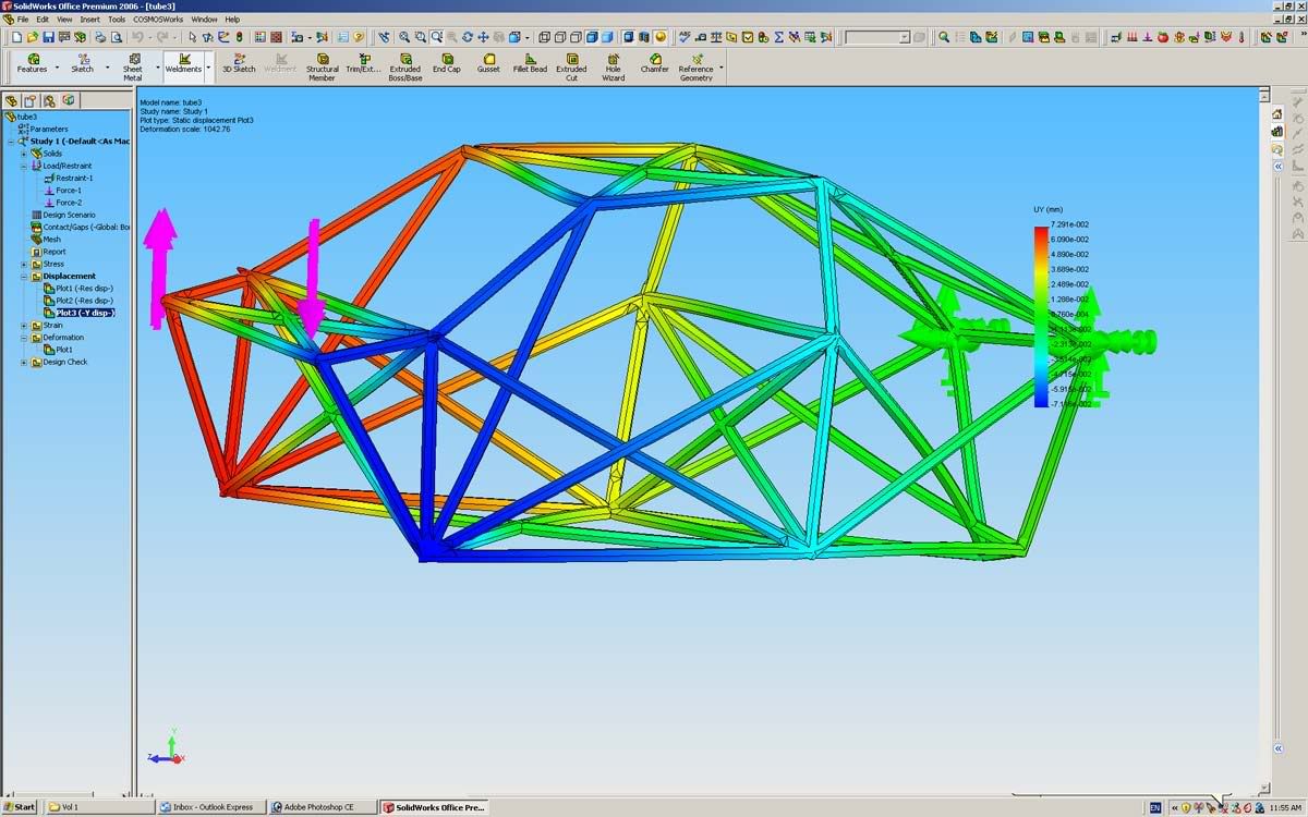
I am getting some very encouraging nubers, just need to check how accurate solidworks cosmos FEA is..
I am also working on a mid engined light weight car using a biek engine... but will post that later when my model is ifnished...
cheers
vlado
Liam - 23/10/06 at 06:24 PM
oooh that looks interesting!!
I've got sw 2005 and it wont let me stress my chassis as it's made from weldments which are all separate solid bodies. Does 2006 not have
this limitation or is there a way to merge the weldments to one solid body? Or is that the full version of Cosmos with more features? (not just the
cosmos express demo).
Liam
Alan B - 23/10/06 at 06:40 PM
My guess is it's the full version because he's using SW office premium which includes the full version.
chriscook - 23/10/06 at 07:09 PM
kikiturbo,
Welcome to locostbuilders.
Please don't take this as criticism but your model appears to be over constrained compared to how this kind of thing is normally done. It looks
like your chassis cannot change width at the constrained end. One constraint should be all the directions and the other rear corner only vertically
and longitudinally. What you have done is still very useful to improve your chassis design but your constraints are artificially stiffening the
chassis.
A useful way to determine how efficient a chassis design is it to carry out a modal analysis. I've no idea if Grape or Cosmos can do this type of
analysis tho. The result you get is the natural frequency for different mode shapes (torsion, bending etc) and increases with increasing stiffness and
decreasing mass.
Again welcome to the nuthouse and please don't take this as criticism - I'm just trying to offer some useful advice.
Chris
kikiturbo - 23/10/06 at 07:15 PM
yeah I am using a full office premium version but even that one has problems with FEA on tubing....
firstly, you need to construct your model, easies way is trough weld profiles, but do not "weld" it, but you need to combine all the tubes,
by selecting all the tubing and going
Insert - Feature - Combine
also, SW Cosmos has problems when you model the car using tubing, so I switched to using full bars of the same area as tubing I want to use... now
this is bad because it doesn't simulate tube stiffness in bending bu IMHO it is ok because:
1. it will give you lower torsional stffness,
2. tubing is much much much stiffer in elongation/compresion than in bending so by concentrating on propper triangulation (which you have to with such
a model) you will get better results....
I think Express should work with the method I am using also..
cloudy - 25/10/06 at 02:56 PM
I've struggled to work my way round solid works, if anyone could do a very quick write up for solidworks premium - how to create a few tubes,
then how to constrain and apply force to show the coloured stress diagram as above would REALLY help me improve my design....
James
kikiturbo - 25/10/06 at 11:05 PM
hmm, if I find some time, I might even shoot a short vid clip on how to do it in solidworks... just the basics..
liam.mccaffrey - 25/10/06 at 11:13 PM
http://www.solidworks.com/pages/onlinetour/hiddentour.cfm
click the linky on this page, skip the intro, start tour, click part modeling,click weldments, click view demo
this is a really good tute for building a car chassis out of sw weldments
the other ones are pretty good as well
[Edited on 25/10/06 by liam.mccaffrey]
[Edited on 25/10/06 by liam.mccaffrey]
cloudy - 26/10/06 at 08:52 AM
thanks Liam, i'll have a watch
kikiturbo - sounds great!
cymtriks - 27/10/06 at 07:22 PM
quote:
Originally posted by Liam
And amazed to find out how effective the removable over-the-engine-bay brace is! My engine is wide and mounted far back so I can't have either R
tube in the engine bay. This is why i went for a structural scuttle and the removable brace (see photo archive). Without the brace fitted the
stiffness is only about 1500 ft lb per degree! So that few kgs of structure trebbles the chassis stiffness by itself! Even with two R tubes (purely
hypothetical in my case as they wont fit) my chassis is only 2400 ft lb per degree without the removable frame.
Another significant point is the 'knee bars' that i've fitted from the outside of the cabin by your knees (where it starts to taper
inwards) diagonally forwards to the middle of the inside of the footwell (see photo archive). When I was balsa modelling and fitted the engine bay
frame the whole chassis became stiff apart from this kink in the chassis. I could see the sides flexing out significantly here on the balsa model so
i fitted the 'knee bars' which stopped it. Sure enough the FEA shows that those two tubes alone add 800 ft lb per degree by themselves!
It's worth pointing out though that without the engine bay frame fitted the chassis' wobbliness is irredeemable and these knee bars only add
about 20 ft lb per degree - so only worth adding on a stiff chassis.
Liam
Tube R is very, very, important though in your case you've replaced it with a substantial triangulated structure which is even more effective.
It always worries me when people think they can miss out tube R and it won't matter, it's just one tube...
If you miss it out then replace it with something else!
Regarding the Knee bars I think they probably work in harmony with the rest of the dashborad structure, I don't think that the stiffness of the
rest of the chassis is the real issue here. It's more likely that your dashboard framework is adding a giant triangular box across the chassis
and the knee tubes triangulate one side of that box. Conversely, if there's no triangular box, or no loads being fed into the box by the engine
bay top structure then the knee tubes do nothing much at all.
The region behind the seat could be turned into an even bigger triangular tube across the chassis, you just need to add a couple of diagonals on the
seat back and on the face at the rear of the chassis.
Wel done by the way
JB - 28/10/06 at 11:43 AM
Its so nice to read that somebody has played with a balsa wood model of their chassis to optomise it.
Its amazing how much you can learn with just a few bits of wood!
John
DanL - 3/11/06 at 02:43 PM
I don't mean to be critical but in my experience Cosmos and similar programs do not produce as accurate results as the obviously more pricey
dedicated packages. Saying that they can provide information which is of course useful! In addition, to gain the most accurate results the element
type needs to be selected with care. Modelling tubes with thicknesses can produce inaccuracies. I'm hoping to do some work in ANSYS soon. Nice
work tho, nice to 'meet' people with the same interests. Keep us posted on any developments!
cymtriks - 3/11/06 at 09:31 PM
The element type is less important than specifying the elements properties. At least at the locost level of modeling.
As long as the properties are correctly chosen a beam, bar or strut should be fine for a spaceframe.
The real reason that cheaper packages have a bad reputation, along with drawing package FEA plug in options, is that the operators don't have any
real experience and think that you just point and click on the right buttons and off you go. It's very easy not to appreciate the maths behind
the problem and how that relates to a real part. The operators have been told how easy FEA is so they blame the software for screwing up when the real
problem is they haven't a clue.
It takes years of experience to get really good at FEA and at the more senior levels a lot of hand editing of input decks and sometimes purely hand
written decks are still carried out. Most of my input decks are a mixture of auto and manual mesh. I'm close to completing an analysis that has
taken six months (a casting containing three bearings in which a shaft is mounted) and before that I spent six months looking at a spline and a nut (a
very special nut to take very high loads with large load changes and severe thermals but still just a nut when all said and done).
Then there are all the little things you need to know, Abaqus for contact, Nastran for structures and Ansys for non linear is a fairly traditional
split of capabilities but then you need to know the difference between a beam orientation vector in one package and another. And do you want stiffness
or stress or vibration? And they keep changing them too. Nastran changed a default on shell elements a while back.
They don't tell you that on the typical two day FEA "instant expert" training course, they'll pretend it isn't true, but
then the tutor has probably spent his entire career just pointing and clicking to fill nice simple shapes with tetrahedral elements.
I've been on a Nastran course in which the tutor instantly appreciated why we used simple models for some very complex parts and complex models
for some very simple parts but the UG stress package tutor had to have it explained to him that some problems are not best solved by pointing and
clicking on the "fill with tets and forget" button.
cloudy - 8/11/06 at 03:33 PM
Having two problems with solidworks.
Firstly, i can create the base of the chassis fine, sketch it, dimension it then convert to structural member in tube.
I dont know how to draw in the other planes though, & how do I create tubes at compound angles?
The other problem is as i make the chassis bigger, even with it all made as "combine" the COSMOS moans about the volume mesh failed???
Any pointers or a chassiss file I could open to play about with?
James
Mad Dave - 8/11/06 at 03:51 PM
I generally create the whole chassis as a 3d sketch, constraining the line coincident, colinear and parallel etc. Doing it this way you avoid having
to create planes to sketch on for nearly every chassis member.
U2U me if you need any help
kikiturbo - 9/11/06 at 12:50 PM
for solidworks, I always first create the end points in 3D space, then just connect them with lines... this takes some calculation but works great..
in other words I am always sketching in 3d
as for volume mesh fail... i had the same problems, then switched from using tubes to using solid bars of the same cross section.... does not simulate
bending stiffness well but you do not want to rely on tube bending for your frame stiffnes, but rather, with propper triangulation, on the stiffnes
that you get from tube compression/elongation and that you can simulate well with solid bars...
send me you email an I will send you a model as an example..
cloudy - 9/11/06 at 09:20 PM
any luck on a video tutorial kikiturbo?
I can create the whole chassis in 10mins in 3dsmax, but I've spent the last hour just trying to make a basic 3d shape in tube!! 
James
kikiturbo - 10/11/06 at 08:28 AM
sorry for the delay, I just had a friend total my brand spanking new Pug 206 GTI180 this weekend so I have been busy with other things... 
will put something togeather this weekend...
cheers
vlado
cloudy - 10/11/06 at 09:22 AM
 damn
damn
DanL - 10/11/06 at 11:53 PM
I initially created the bottom rails on the reference planes given, and then offset another plane parallel to this at the top rails height. Working
with these I managed to used the 3d Sketch tool to generate the rest of the geometry. I then converted everything to a single 3d sketch to make things
easier. I used the structural member tool for some straight tubes but the tool mitres the joints instead of placing a radius on the other tubes. I
used the 3d sketch of the full chassis to create separate 3d sketches of each tube axis. I can then simply locate them exactly within the assembly and
there are no worries of poor constraints.
Gutted about the 206, I'm taking my 106 rallye to Cadwell Park in mid december...rather worried about doing something similar! Should be a good
learning experience if it isn't icy!
[Edited on 10/11/06 by DanL]
Anman - 6/12/06 at 12:51 PM
I am having some problems with solidworks. I am designing a chassis with the weldment features. This gives me two problems:
-Cosmosworks sees every part as a body and can only analyse 1(!) body at a time.
-I only design one half of my chassis and mirror the rest. How do i make sure the faces at the mirror plane are joined?
tnx
ZEN - 6/12/06 at 03:46 PM
@cloudy
Take a look here http://www.3dcontentcentral.com There is a space frame chassi in the
MISCELLANEUS/AUTOMOTIVE section. I'v got some video tutorials for solidworks but are too big for mailin them (250MB). I sent you a U2U message
for the link 2 download 
[Edited on 6/12/06 by ZEN]
Anman - 6/12/06 at 08:38 PM
What would really solve my problem is the possibility to make one body out of multiple bodies so i can do some quick analysis.
pgpsmith - 7/12/06 at 05:05 AM
I haven't tried this with weldments, but have you tried opening the Solid Bodies folder near the top of the feature tree, Control click on
several bodies, right click and select "join bodies" or "merge bodies", or whatever the words are?
(another) Pete B
Anman - 7/12/06 at 03:50 PM
There is no such option for weldments...
Mad Dave - 7/12/06 at 04:02 PM
If I remember correctly, open the cut list file and select the bodies you want to join. Right click and "Combine". You should be able to
"Add" the bodies to make one. Update the cut list and right click on this combined body and insert into a new part where you might be able
to use Cosmos on it.
With Solidworks you don't get the full Cosmos package, its an Addin that you have to pay for
Dave
Anman - 7/12/06 at 05:15 PM
Ok that worked. But i found out my version of cosmos sucks.
I'll geuss i be using some free fea package. Any suggestions?
BlackSheep - 8/12/06 at 01:36 PM
Heyz Anman,
Welkom gozer ;-) If you look on isohunters dot com (Torrent search site) you'll be able to find a full Solidworks 2007 Office Premium Edition DVD
image, with keys. There's a full version of Cosmos Works on there too. Including keys ofcourse... I guess there's no harm in using it just
for educational purposes? 
kikiturbo - 14/12/06 at 02:33 PM
ok, I finally found some time to do a quick tutorial on FEA on solidworks... now, this is very basic but I find it very usefull..
I firstly have to appologize to all the FEA professionals out there, as this is a very basic description of a very complex science.. but as I will
say, this is just to enable people to have a better grasp on the chasis they are constructing...
first of all, let me make something very clear..
I do my modeling by using solid bars instead of tubes for my spaceframes... I use the bars of equal cross sectional area as the tubing I want to use,
so to have the identicla properties in tension/compression, but this way I do not simulate te tube bending properties correctly.. but, I do not care
and here is why
1. spaceframes should be optimised for tension and compression in the tubing, as it is much stiffer that way... if you do so, the difference between
the real stiffness and projected stiffnes will be minimal.
2. the model will not be "optimistic", i.e. real stiffnes will be greater than that you get from the FEA
3. Cosmos has problems when modeling the tubing, it is usually very slow, and has a lot of errors when you use tubing..
4. using bars is much much faster... you get results almost instantly...
also, I do not like to be 100% precise with my model, I prefer to use a bit simplified model (meaning just the tubing, no brackets or similar) so that
I can work faster and optimize my model first, then go for the nice final model and check the clearences etc..
so here we go..
1. use the Sketch mode, 3d sketch and place the hard points in your model... this basically includes all the tube endpoints you plan to have. I
usually sketch my chasis on paper first, with all the measurements first, that way I have all the points ready to enter into the solidworks by hand...
Then I use the line tool and connect my hardpoints in the same way I want to put tubing later... you end up with the spaceframe...
http://img.photobucket.com/albums/v723/turbolimac/solidworks/3.jpg
http://img.photobucket.com/albums/v723/turbolimac/solidworks/2.jpg
http://img.photobucket.com/albums/v723/turbolimac/solidworks/1.jpg
2. Time to add the tubing... or bars in my case...
Use the Weldments option, and click on the structural member...
http://img.photobucket.com/albums/v723/turbolimac/solidworks/5.jpg
you have to choose what type of structural member you want... as I sadi I use full bars of the same area as my tubing... For the tube of 50x2 mm you
need 20 mm dia bar.
in the solidworks you allready have some structural member profils you can use, but you can also define your own, like I did. It is very simple and
very well shown in the SW tutorial.
so after choosing the profile you want, you just click on the line you want ot run the profile trough and that is it... you can also run a continous
profile trough several lines and that is good practice as the software wil ltake care of joints and you will not have "holes" in the joints,
such as this:
http://img.photobucket.com/albums/v723/turbolimac/solidworks/20-1.jpg
holes are no good as they will cause errors when generating a mesh for the model... during the FEA analysis..
It is good practice, because of this, to run a continous profile trough the "outside tubes" that way you will have no holes.. for example,
on my model I run continuous profiles as highlighted on the model by red and green arrows..
http://img.photobucket.com/albums/v723/turbolimac/solidworks/8-1.jpg
http://img.photobucket.com/albums/v723/turbolimac/solidworks/7.jpg
http://img.photobucket.com/albums/v723/turbolimac/solidworks/6.jpg
3. Combining..
when you make a model with weld profiles SW still doensn't understand it is one single body... so you have to combine the tubes...
http://img.photobucket.com/albums/v723/turbolimac/solidworks/10.jpg
you select all the structural members in the list on the left, and go Insert - features - Combine
4. Defining planes...
This is a good time to define the Planes that you will use to orient the forces that you apply on to the body.... Planes have to be perpendicular to
the forces.. you define them by using the plane tool, and you can choose either three points or a line + 1 point, etc..
Since my model tubes that are paralel to the ground, I just use the lines in my model to define the plane..
http://img.photobucket.com/albums/v723/turbolimac/solidworks/12.jpg
http://img.photobucket.com/albums/v723/turbolimac/solidworks/11.jpg
5. FEA.....
ok, time to see what you desinged...
there are a number of things you can see and calculate by using the FEA... as car "builders" we are primarily interested in:
- torsional stiffness
- chasis bending
- stress analisys..
so, to calculate these we need: chasis model, restraints (i.e. points that are fixed to an imaginary hard point), force inputs, definition of material
properties...
1. lets define the material
http://img.photobucket.com/albums/v723/turbolimac/solidworks/21.jpg
so, it is right click on the combined body (as shown in the list on the left) and go to material properties, and choose material of choice...
--next we have to define the restraints...
so, click on the restraints menue, and then choose the points that you want fixed... I chose the upper spring/damper mounts.. as they carry the weight
of the car in the rear... you need to click on the edge of the joint or the tube going across or similar..
http://img.photobucket.com/albums/v723/turbolimac/solidworks/15.jpg
http://img.photobucket.com/albums/v723/turbolimac/solidworks/14.jpg
-- apply the force...
to study the torsionall stifness you need to apply the force on the front spring mounts.. you can either apply opposing forces on the left and right
mount, or, put a restraint on one of them and force on the other.....
http://img.photobucket.com/albums/v723/turbolimac/solidworks/17.jpg
http://img.photobucket.com/albums/v723/turbolimac/solidworks/16.jpg
-- meshing...
for the FEA you need to define a mesh... so you just click on the mesh icon, and then generate the mesh... you can play around with the mesh size..
of course..
http://img.photobucket.com/albums/v723/turbolimac/solidworks/24.jpg
http://img.photobucket.com/albums/v723/turbolimac/solidworks/18.jpg
after that, you just run the calculation, and then you can see the results for the static analysis, for strain, and most important for torsional
stiffness, displacement... as this will give you the info to calculate the torsional stiffness of the chasis..
http://img.photobucket.com/albums/v723/turbolimac/solidworks/25.jpg
the formula for the torsional stiffness of thechasis... right off the top of my head, subject toconfirmation (as I have to leave my office in a hurry
) is:
using two opposing forces F
torsional stiffness = F / arc sin (displacement / distance between the forces)
cheers
vlado
p.s. for some reason the thumbnails from photobucket doesn't work...
p.s.s I now see that photobucket has made the pics smaller, if you have trouble with this I will host the pics somewhere else..
[Edited on 14/12/06 by kikiturbo]
[Edited on 14/12/06 by kikiturbo]
ZEN - 14/12/06 at 03:53 PM
You got U2U
Anman - 18/12/06 at 02:09 PM
Very nice tutorial, now only need to get a copy of the full version of cosmosworks..
kikiturbo - 18/12/06 at 09:29 PM
cosmos that is included in the SW will work in a similar fashion... I only noticed that it is more difficult to add restraints, but I think one can
work around it...
I hope I will finish the design on the integrale chasis, so that I can show you why I like to do quick FEA analysis on the chasis as there are a
multitude of different desing choices one can make..
kikiturbo - 21/12/06 at 09:32 AM
chriscook - sorry, I just yesterday saw youtr reply.... of course you are right, and thanks for the tip... although, my restraint model had to do with
the way we test torsion over here and we indeed fix the rear flat to the wall, so it is restrained in all directions... I guess that with the rear
"plate designed in the way I usually do, with full triangulation, it is not such a difference..
on a similar note... I did some more work with cosmos and found an error in the way I do things..
I used a solid body mesh of my chasis.. which will not mesh every time... it seems that when you have a lot of triangulation SW has errors while
meshing... (Edge gap too large error..)
so I switched to Shell mesh using surfaces..
http://img.photobucket.com/albums/v723/turbolimac/solidworks/shell1.jpg
you define the type of the mesh when you create a new study,...
the good thing about it is the following..:
when defining the shell mesh you also have to define the thickness of the shell so in esssence you define your tubing thickness... so you still draw
the model using full profiles (makes combining possible, SW will not combine the model when you have hollow tubes in the model..) but then when
defining the mesh you define shell thickness - tube thickness..
in my example I am using 40 mm dia 1.5 mm thick tubing.. so, it is 40 mm dia full profile, and then I define my surface mesh as 1.5 mm thick..
now for an example, just to show the benefits of quick FEA analysis..
please note that the ends of the chasis where suspension attaches are not fully modeled, this is just to experiment with the general chasis shape..
for my single seater BEC middy I first started with a "classic" narrow frame:
http://img.photobucket.com/albums/v723/turbolimac/solidworks/proba1tubing3.jpg
this gave a structure of about 56 kg and aprox 3600 Nm/deg in torsion... (IIRC)
the displacement pic has shown that front and rear are very stiff but I had a lot of bending in the driver compartment..
http://img.photobucket.com/albums/v723/turbolimac/solidworks/proba1-tubing3-Study-1-Disp.jpg
then I added an outside triangle that stiffens the driver compartment... I also removed some of the tubing in the back
http://img.photobucket.com/albums/v723/turbolimac/solidworks/proba1sketch3tube40.jpg
and hey, 13000 Nm/deg stiffness and only 2 kg more.. also there seems to be a more uniform twist troughout the chasis..
http://img.photobucket.com/albums/v723/turbolimac/solidworks/proba1-sketch2-tube-40-Stud.jpg
cloudy - 21/12/06 at 02:02 PM
excellen tutorial - now just need to get to grips with the sketching - i'm fine in one plane, but soon as it starts affecting more than one it
all goes very wrong
James
kikiturbo - 21/12/06 at 03:41 PM
just define the points manually, by writing in the coordinates in 3d sketch... then it is a piece of cake...
