
Suspension and Chassis for CANAMSA
Fred W B - 31/8/14 at 05:54 PM
Evening all
Those that have followed my Bodywork for Canamsa thread will know that I have got
the body just about finished.
For various reasons I have not reported any significant progress on my project this year yet, but I'm hoping that will change now that I am over
the hurdle of the rear uprights. This turned out to be a very long story which needed facilities that I do not have in my garage and took a lot of
running around to sort.
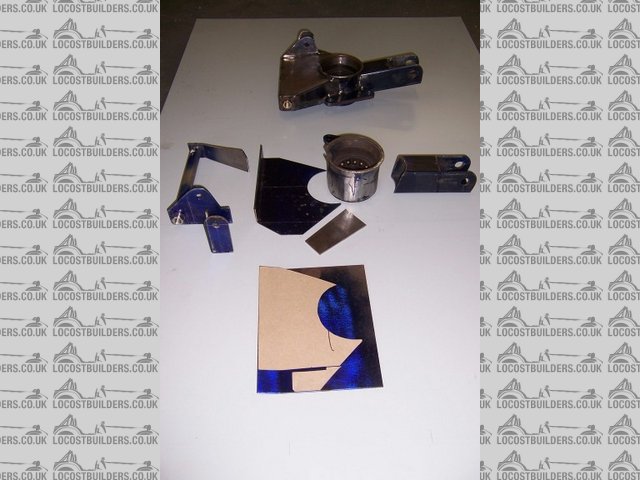
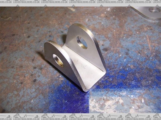
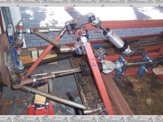
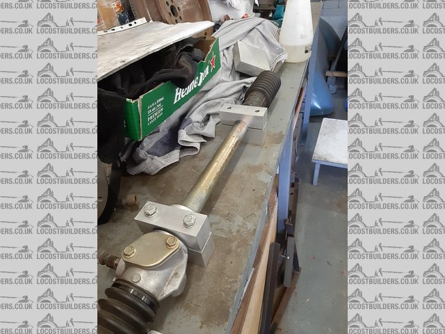
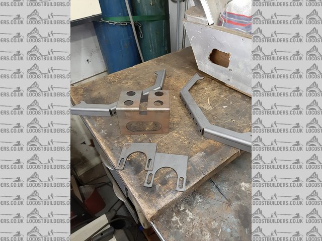
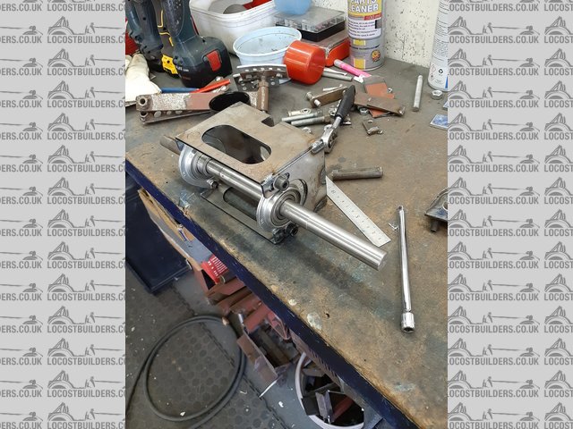
I started to fabricate these around the bearing housings cut out of the front struts from the Audi that donated the transaxle. In these pictures you
can see the parts and a tube that self jigs the lower bushes in line with each other and the side walls vertical.
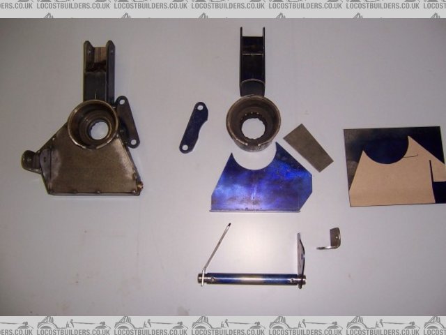
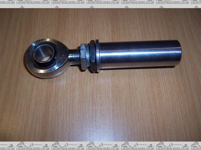
I intend to make the real wishbones from 21.3 od x 2.11wt Schedule 10 stainless tube, with machined inserts plug and fillet welded into the ends. You
can see the detail in the pic below. I have also used this detail inside the bottom of the uprights. The joints are M12.
I tacked the parts together and took them to a friend (man 1) to be TIG welded up. I left the old bearings in in what turned out to be a vain hope
that they would help prevent the housings distorting too much. Getting the old bearings out was difficult, this was eventually only accomplished with
the aid of a big press and welding on the race by a car repair shop (man 2 and 3). The housings were up to 0.5mm out of round in places.
So this needed to be sorted. I bought new bearings to measure from a friend at a bearing suppliers (woman 4) who recommended a workshop that might be
able to help (man 5). Talked to man 5 who took an interest in my project, but could not help and suggested I go to a machine shop nearby (man 6). Man
5 even phoned man 6 to tell him to expect me. Man 6 turned out to be the proprietor of a fair size industrial machine shop and who also builds and
races V8 dirt track cars as a hobby. He told me to leave the housings with him.
In the meantime I had drilled the hubs to convert to Ford PCD and studs, which necessitated visits to another friend (man 7) to use his small lathe to
cut the "as cast" rear face of the hubs and then back to man 1 to press in the new studs.
Man 6 called to say the uprights were finished. He had cut a true reference step in one end of the housings, made a fixture to hold the uprights in a
lathe, turned them to a true size and matched them to the bearings. He refused to accept any payment for all of this.
So now I could take the uprights home to fettle some of the welding a little and then to a paintshop (man 8) to have them sand blasted and painted
black.
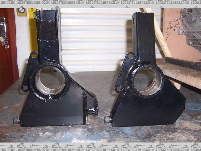
Then back to man 6 who light press fitted the bearings and hubs and finally I could test fit the brakes and see how they looked in the wheels.
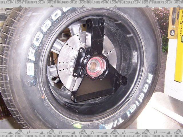
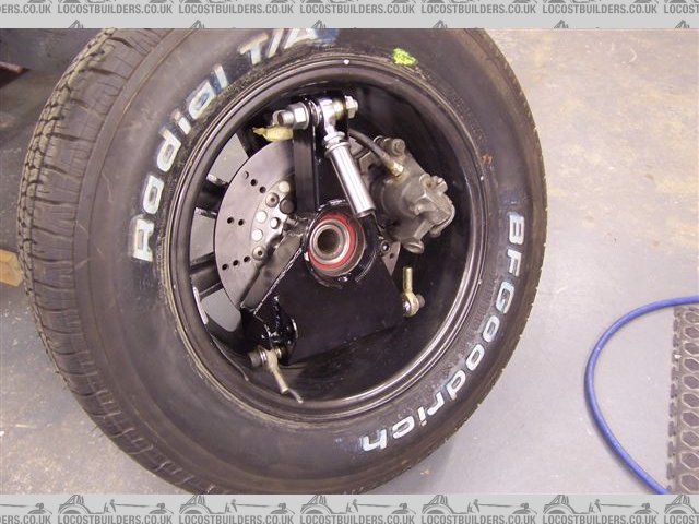
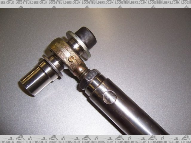
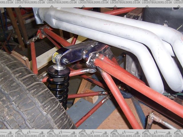
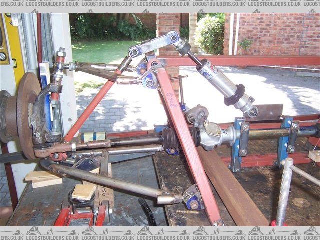
The top M16 attachment incorporates a internal and external threaded bush between the left hand 1.5 mm threaded rose joint (sourced from McGill
motorsport U.K.) and the bush that will be welded into the top wishbone to give camber adjustment. A 360 deg rotation gives 3 mm of movement. The
black half nut is the locknut on this adjustment bush, the lock nut on the rosejoint is not fitted yet. These parts were sourced with help from yet
another friend (man 9).
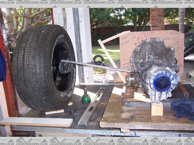
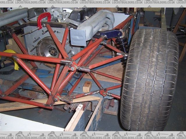
And finally I could mock up the wheel to trans axle geometry assembly. With a rear ride height of 125 mm It looks like I will get just on 10 deg drive
shaft angle.
Cheers
Fred W
[Edited on 31/8/14 by Fred W B]
HowardB - 31/8/14 at 06:18 PM
Fred,
this is going to be awesome, I can already tell that 
I shall look forward to every single update in the knowledge that I shall learn lots
ceebmoj - 31/8/14 at 06:21 PM
Great to see you making progress. Its amassing how long it can take to get jobs like this done, having said that it sounds like you have made some
good contacts for the rest of the build.
mark chandler - 31/8/14 at 06:25 PM
On the home straight, well done for preserving as many would have fallen by the wayside.
Are you going to get the half shafts chromed to complete the look?
TheGiantTribble - 31/8/14 at 06:34 PM
So glad to see this continuing amazing build
I feel certain every update will leave me mesmerized, all of them so far have.
Ivan - 1/9/14 at 07:23 AM
I will certainly be following this Fred.
James - 1/9/14 at 03:02 PM
Following this too- as you know Fred, I have aspirations towards my own replica build!
Fred W B - 1/9/14 at 03:56 PM
Thanks for all the responses
quote:
sounds like you have made some good contacts for the rest of the build.
Yes, although when people do things for me for free or almost nothing I don't like to bother them too much or take advantage. So I try to spread
it around.
quote:
Are you going to get the half shafts chromed to complete the look?
Not actually, I'm planning on keeping the "bling" to a minium. The choice of stainless steel for wishbones is down to me being able to
source the schedule tubing easily. It's pressure rated and so must be better made than ordinary carbon steel tube. Chrome Moly is not easy to
find in these parts.
Cheers
Fred W B
[Edited on 1/9/14 by Fred W B]
mcerd1 - 2/9/14 at 08:47 AM
quote:
Are you going to get the half shafts chromed to complete the look?
Not actually, I'm planning on keeping the "bling" to a minium. The choice of stainless steel for wishbones is down to me being able to
source the schedule tubing easily. It's pressure rated and so must be better made than ordinary carbon steel tube. Chrome Moly is not easy to
find in these parts.
You could put a satin finish on them when your done rather than polish them
I think it would make it look more 'engineered' and a lot less bling
Fred W B - 2/9/14 at 04:30 PM
quote:
You could put a satin finish on them when your done rather than polish them
Yep, the finish will be bright electropolish. The schedule pipe is not 100 percent smooth like "dairy" pipe or a chrome finish, you will
still see some texture on the material surface.
Cheers
Fred W B
ceebmoj - 17/11/14 at 07:52 PM
Hi Fred, How are you getting along? I was just reading through the body work thread again and was reminded to check in hear for progress.
Fred W B - 18/11/14 at 05:36 PM
Hi Ceeb
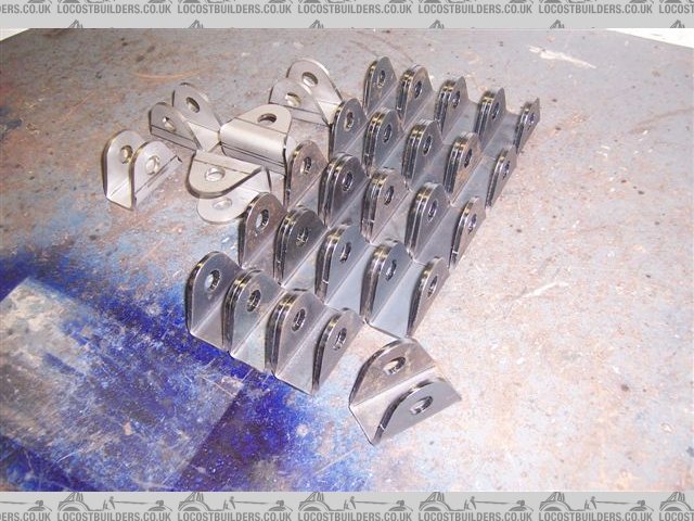
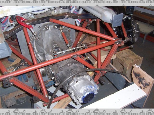
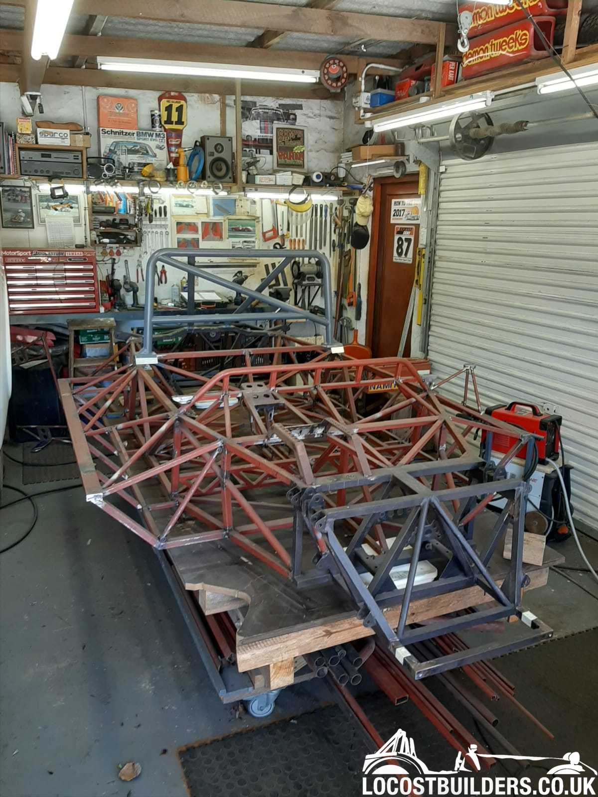
Thanks for the interest. Although I have now got the rearmost section of the chassis and rear suspension pretty much laid out none of it is yet up to
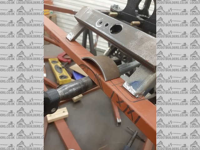
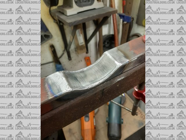
the final, real part stage. Although at least I got a batch of suspension attachment brackets made.
Have spent much time deliberating over material thicknesses, and tube sizes and things like
this. I tend to want to over engineer everything and am trying hard to
keep the details light and simple.
Also done quite a lot of fiddling with a prototype gear linkage.
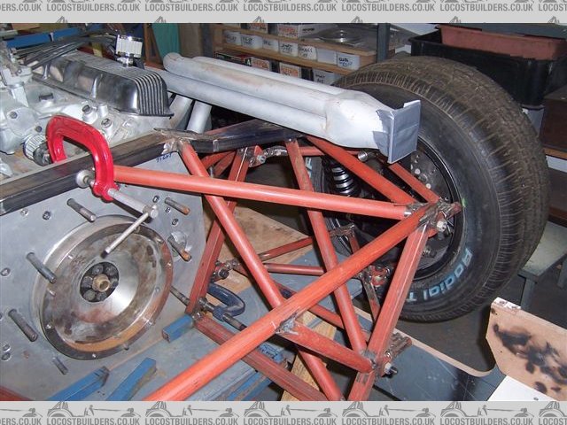
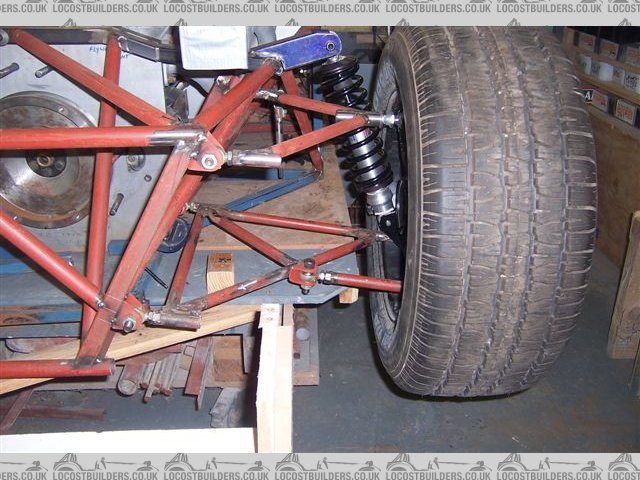
Some photos, note that this is still mock up work, chassis braces fitted on one side only and the wishbones shown are very rough representations in
small tubes.
Cheers
[Edited on 18/11/14 by Fred W B]
Ivan - 19/11/14 at 11:55 AM
I have got to come see this all when I pass through PE Fred.
Keep up the VERY good work.
How close to the original suspension geometry and chassis design are you able to get - or is it all your own design?
Ivan
[Edited on 19/11/14 by Ivan]
Fred W B - 19/11/14 at 04:34 PM
Thanks Ivan, you are welcome to come have a look.
At this stage I am not intending to attempt a replica tub chassis, maybe that will be a longer term project. The original had rear suspension with
long rear radius rods, single upper link and reversed lower wishbone as in GT40.
I'm doing a space frame with rear upper and lower wishbones so the rear of the chassis and suspension is nothing like the original.
If you want to replicate the original geometry exactly you are into using wheels and uprights as per the originals and that gets spendy very
quickly
Edit - now that I have added the picture below I see that at least my coilover is in just about the same place 
Cheers
Fred W B
[Edited on 19/11/14 by Fred W B]
[Edited on 19/11/14 by Fred W B]
ceebmoj - 2/12/14 at 08:46 PM
Looks like you are making great progress Fred. Have you seen gtrclive's
build over on PH? I ask because the way the rear frame on your car reminded me a bit of his build.
[Edited on 2/12/14 by ceebmoj]
Fred W B - 3/12/14 at 06:27 PM
Hiya Ceeb.
Yes, I do look in on Clive's build from time to time, you could say it is somewhat more sophisticated than what I am doing 
Cheers
Fred W B
Fred W B - 23/3/15 at 07:17 PM
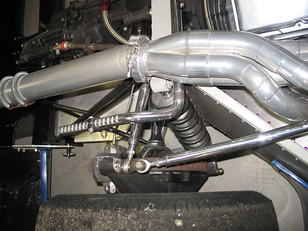
So I've spent quite a bit of time mocking up the front suspension, and I'm starting to think about trying to make an inboard mounting for
the coilover work.
The major issue it will solve is that, with the coilover in the conventional position, I can't use all of the damper travel of the units I
already have. Plus positioning the coilover so it can be mounted at something like a sensible angle, and still clear the top wishbone was problematic.
Another advantage of the inboard setup is that the pushrod length can easily be altered, to give a wide range of ride height adjustment. This mock-up
bell crank has ratios that give a one to one relationship between wheel travel and coilover displacement.
I am aware that I will have to engineer a decent pivot detail in the rocker arms, unless I can find something off the shelf. Anyone know what bearings
Ariel or other manufacturers with a successful detail use?
The wishbone attachment brackets will be made wide enough so I can adjust the castor from 5 to 10 deg by shimming the inner mounts. With a fullbody
car I need to keep the wheel in the centre of the wheelarch so both the top and bottom attachements need to have this detail. 
Cheers
Fred W B
[Edited on 23/3/15 by Fred W B]
Andybarbet - 17/4/15 at 08:27 PM
A bit off topic Fred but if you get to watch any of the goodwood 73rd members meet on catch up tv, there's some T70 lola's racing -
it's fantastic :-)
Fred W B - 20/4/15 at 03:03 PM
Hi Andy
Thanks for the tip, Ill keep an eye open for that.
Cheers
Fred W B
ceebmoj - 6/5/15 at 09:20 PM
Hi Fred, have you made any progress? I look forward to seeing how you are getting on.
Fred W B - 17/5/15 at 06:22 PM
Hi there
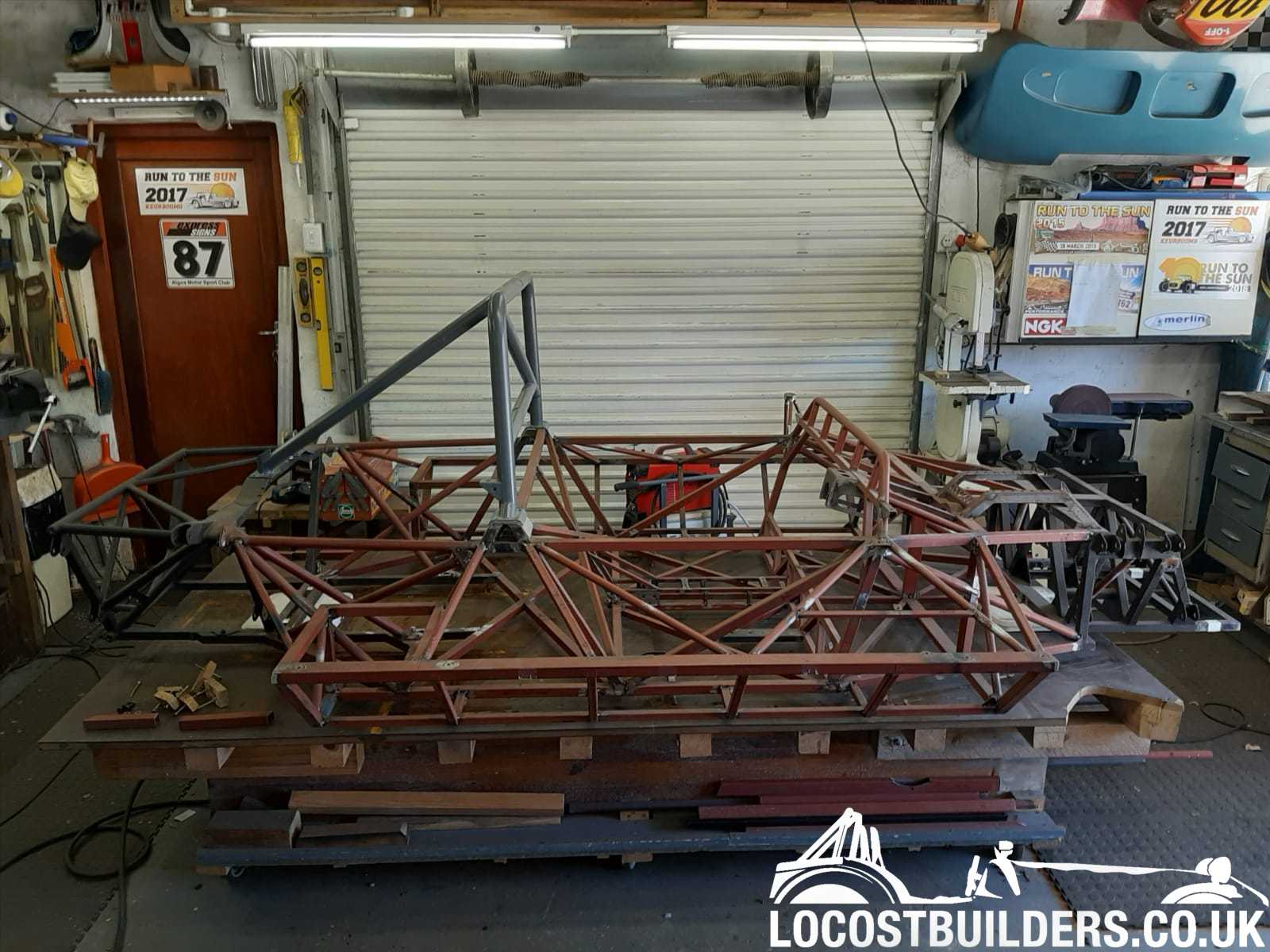
Cant offer much of an update, it seems that I've got a bit bogged down in trying to finalize too many details all at once, suspension, radiator
size/placement, roll bar shape/height and possibly the most problematic being the position of the fuel tank/s. Im not keen to put them alongside the
driver/passenger.
I've now decided against the fuel tank position shown in the pictures, it's right on the perimeter of the car so very close to an accident.
Also very close to the engine/exhausts. Now planning to put all the fuel inside the chassis, behind the seat bulkhead. Need to decide how much fuel
capacity is enough - 50 L, 70 L?
Hoping to start welding up the real chassis pretty soon. Some of the chassis members are not represented in these pictures.
Cheers
Fred W B
[Edited on 17/5/15 by Fred W B]
[Edited on 17/5/15 by Fred W B]
[Edited on 17/5/15 by Fred W B]
MikeR - 2/9/16 at 10:09 AM
Hi Fred - its been a long time since an update, have you made any progress?
Fred W B - 4/9/16 at 07:53 PM
Hi Mike, thanks for the interest.
I have made some progress, albeit slow, as I have not been able to devote much time to the project over the last while.
Also been having some issues with my home computer / internet access / photo uploading hence lack of updates.
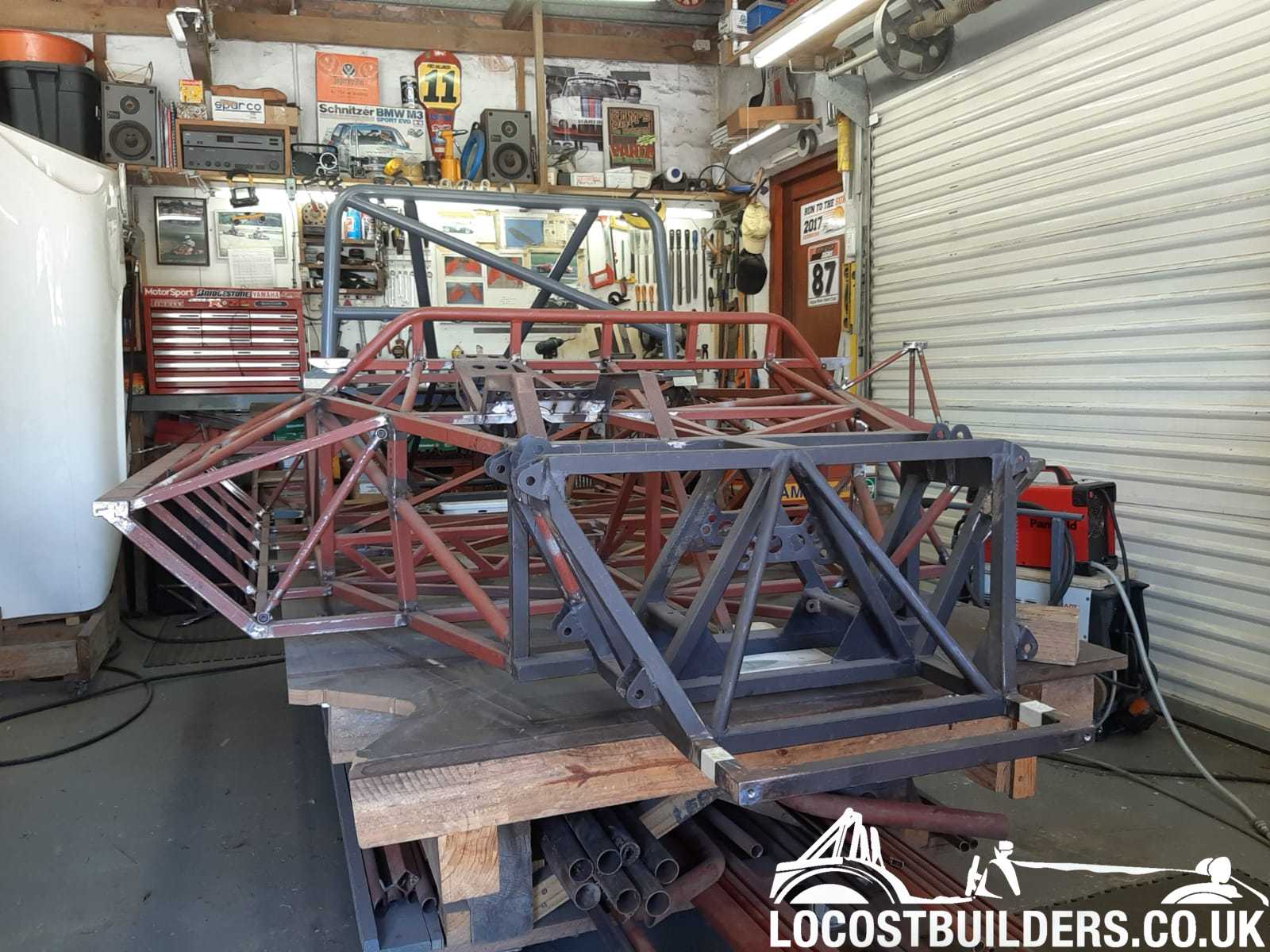
Currently on the real chassis I have:
Most of the centre and rear section tacked up and partially welded.
Dashboard bulkhead fully welded.
Most of the side sills support structure tacked up.
The rear suspension attachment section made up and fully welded. This section is bolted to the main chassis and the engine to gearbox adaptor plate so
needed lots of fiddling with threaded bushes etc.
The rear body section mounting and hinging detail support frame tacked up.
Forward engine mounts tacked up.
In equipment news I have recently treated myself to a proper TIG welder, I need more practice with that.
I'll try to upload some pictures later in the week.
Cheers
Fred W B
ChrisLeary - 5/7/17 at 11:46 AM
Hi Fred,
I've just read your complete build thread so far... absolutely incredible.
I noticed your last post was almost a year ago, how's the build going? I'm excited to see where you are with it!
ATB,
Chris
Fred W B - 6/7/17 at 06:34 PM
Hi Chris
Thanks for the comment, while I have not given up of the project, tangible progress has been very slow of late.
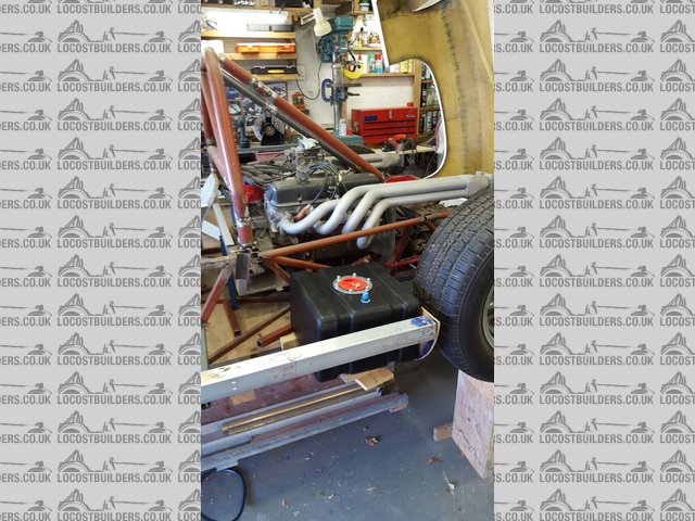
All I can offer as an excuse is that I have been doing a season of Karting

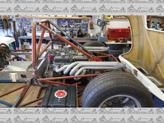
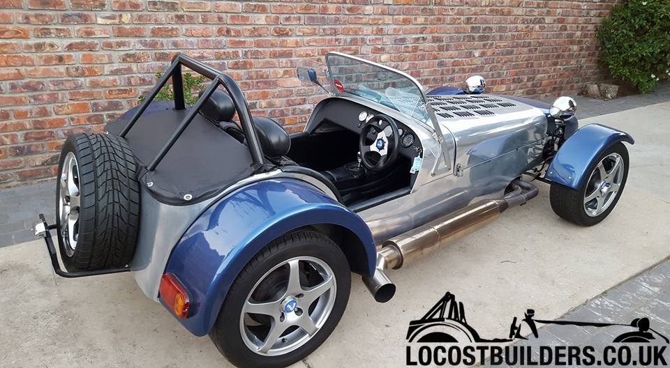
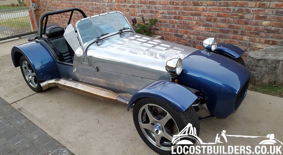
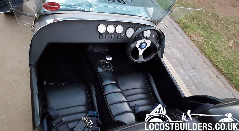
and that I recently bought a Birkin 7. It was built some years ago and has a few things that need to be sorted out. If you can't guess from the
exhaust it has a Mazda RX7 rotary drive train. These pics are just after it was delivered, and yes the wind deflectors are on upside down and a mirror
is missing.
[Edited on 6/7/17 by Fred W B]
Fred W B - 18/1/21 at 07:33 PM
Finally a mention of some progress. I got distracted by a extensive mechanical rebuild of the 7 I mentioned above, but that should be the subject of
a different thread.
Eventually I can unscrew the 99 percent finished tacked up space frame from the build table and weigh it. Very roughly (on bathroom scales) it weighs
110 kg / 243 lbs. without the roll bar and 123 kg / 271 lbs. with. That includes all mounting brackets for the suspension, steering system, pedal box
etc., as well as in the order of 60 internally threaded bushes and weld nuts as attachment points for such as engine mountings, seatbelts, the front
and rear body and door hinge mounting subframes, and the detachable rear chassis section.
Still lots of welding to do, but it does feel like this is another milestone I am pleased to have reached.
[Edited on 18/1/21 by Fred W B]
adithorp - 18/1/21 at 10:11 PM
Good to hear from you again Fred.
jps - 19/1/21 at 05:22 PM
The bodywork thread was great, so good to see things still rolling forward!
Fred W B - 20/1/21 at 05:51 AM
Thanks for the responses guys, Ill try to update more frequently this year
Cheers
Fred W B
swanny - 20/1/21 at 09:02 AM
Id love to see a thread on your Birkin upgrade too! love your work.
Fred W B - 13/6/21 at 06:06 PM
[Edited on 13/6/21 by Fred W B]
adithorp - 14/6/21 at 09:04 AM
Damn! Thought we'd got an update 
jps - 15/6/21 at 07:52 AM
quote:
Originally posted by adithorp
Damn! Thought we'd got an update
me too!!!!
Fred W B - 15/6/21 at 11:13 AM
Hi guys
Sorry about the false alarms. As is obvious I haven't been posting many pictures, I'm trying to find an easy way to resize / host multiple
phone pics but not having much luck.
Regards
Fred W B.
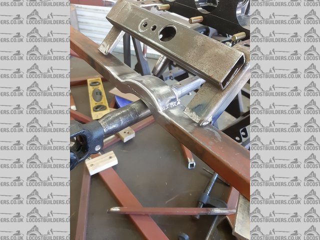
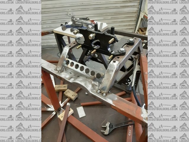
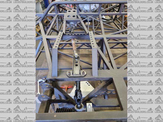
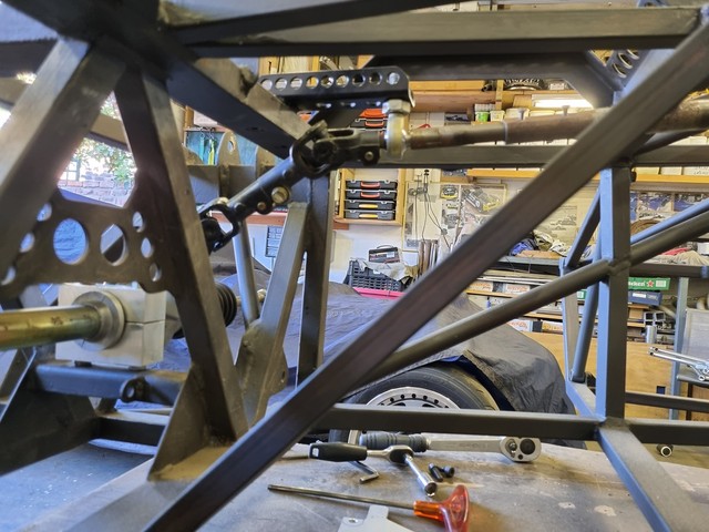
Fred W B - 17/6/21 at 11:00 AM
Steering column and pedal box.
One of the challenges on a scratch build mid-engine chassis is packaging the pedals, steering column and rack, front suspension and your feet that all
want to be in the same space.
I decided to go with top hung pedals, as I want the seats to be formed in the center section of the chassis mono style and that necessitated a movable
pedal box so that people taller than me can drive the car comfortably. Top mounting means that some structure is required and although I try to keep
things simple they always seem to run away with me. The steering column was made up from various Toyota Corolla and Hiace parts to mate to the Ford
Cortina steering rack. The Toyota parts give a nice sliding section for length adjustabity and deflection in case of an accident. I also built in some
up and down adjustment for the steering wheel position. Hopefully the photos will explain.
[Edited on 17/6/21 by Fred W B]
HowardB - 17/6/21 at 11:25 AM
great updates
I do appreciate all the thought and effort that goes into making things work well - thank you for sharing!
b14wrc - 5/4/22 at 11:32 AM
Yes I agree, really nice detail.