
Aero pic
tom_loughlin - 7/4/05 at 06:51 PM
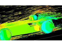
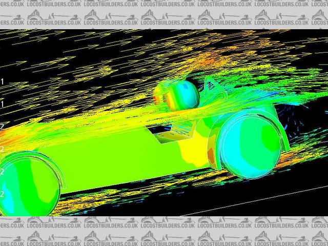
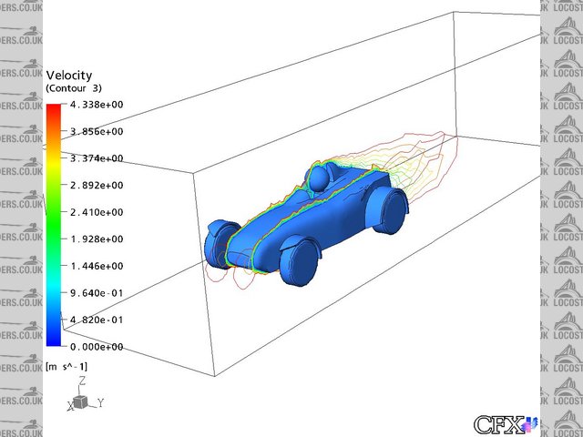
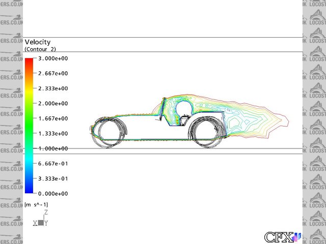
if anyones interested - heres some results of a model i ran through cfx earlier today.
the surface pressure is plotted on the body, and vector plots of velocity are plotted on two perpendicular planes.
you can clearly see a lot of turbulence at the back end, some of which im aiming to eliminate during my dissertation.
the model is a basic model, but its nice to actually gain some results at last.
if anyones interested, i can get some more pics.
im aiming to improve the aerodynamic efficiency as far as poss without changing the design too much
Rescued attachment plot.JPG
Triton - 7/4/05 at 06:54 PM
How would bumps behind each person react ?..........would that clean things up?
Cheers
Mark
flak monkey - 7/4/05 at 07:01 PM
Looking good. For initial improvements (to the back end anyway) take a look at an aero screen (something like the double bubble MK one maybe?) and as
Mark says lotus 11 style raised bits behind the heads.
Whats the flow like around the front? The must be pretty bad....
David 
colibriman - 7/4/05 at 07:05 PM
Good work Tom,
I'm interested in how it goes....
fire some more pictures my way if you don't mind as you progress...
cheers
Colin
tom_loughlin - 7/4/05 at 08:22 PM
hey guys,
for initial solutions i am going to try:
aeroscreen - already mdelled, but not tested yet
riblets - to encourage the flow to remain as laminar as possible over the rear
small bumps on the rear face of the ront cycle wings - to discourage seperation
raised bits behind driver - as you suggest a la lotus 11
the flow at the front isnt great, but i am going to incorporate an upside down 't' section to neaten the flow round the wheels
finally, i think ill develop some sort venturi system with flat bottom to decrease pressure underneath - sucking the car to the ground.
time permitting, i want to investigate boundary layer control - sucking it from the rear of the car.
the hard top i have developed could also do with tweaking along side cfx results.
will post updated pics as and when.
thanks for the comments
Tom
Triton - 7/4/05 at 09:25 PM
'kin ell i understood that.......not
dozracing - 7/4/05 at 09:28 PM
Tom,
The most interesting thing to do would be to model the radiator and blockage to find out what sort of lift this gives. I would really like to know the
most effective position for bonnet and or side panel vents in order to reduce this.
Spyderman - 7/4/05 at 09:54 PM
quote:
Originally posted by tom_loughlin
hey guys,
1: for initial solutions i am going to try:
aeroscreen - already mdelled, but not tested yet
2: riblets - to encourage the flow to remain as laminar as possible over the rear
3: small bumps on the rear face of the ront cycle wings - to discourage seperation
4: raised bits behind driver - as you suggest a la lotus 11
5: the flow at the front isnt great, but i am going to incorporate an upside down 't' section to neaten the flow round the wheels
6: finally, i think ill develop some sort venturi system with flat bottom to decrease pressure underneath - sucking the car to the ground.
7: time permitting, i want to investigate boundary layer control - sucking it from the rear of the car.
8: the hard top i have developed could also do with tweaking along side cfx results.
will post updated pics as and when.
thanks for the comments
Tom
Interesting to see the effects of airflow over the body especially when making changes!
1: This will be interesting especially if you do a normal screen to compare it to.
2+3: You don't want laminar airflow over the rear sections as they will create lift. A ridge going across to cause separation might be more
beneficial, especially on the front cycle wings.
4: Rear body would need extending in order to benefit with airflow or lift properties. Might benefit driver comfort though.
5: Don't understand what you mean here.
6+7: These sound intersting. Looking forward to the results.
8: Please show how hard top result compares with standard.
Please don't take these comments as negatives. I am very interested in seeing the results even though I may have a good idea as to how they will
turn out. Would be as interested even if I'm proved wrong! (highly likely)
Is it possible to do sectional views as well, so that you could see the areas of greatest concern?
Terry

[Edited on 7/4/05 by Spyderman]
SteveO - 8/4/05 at 08:10 AM
Nice work.
Can you please reduce the pic size so as to see whats happening at the nose cone, and possibily post us the progressive effects of each addition,
aero screen, side deflectors, full screen etc.
Keep up the good work and all the best in your degree.
ceebmoj - 8/4/05 at 09:15 AM
I would be intreswted to see youer results as well. if you could post the pictures up in this thred form time to time it would be very intresting
tom_loughlin - 23/4/05 at 08:41 AM
heres some pics of one of the mode i have done - a la d type jag.
the first pic is on the drivers side - with the bump. you can see from the velocity vectors that the flow attactes together more quickly than in the
case without. N.B. i have also banked out the passenger space.
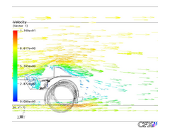
Rescued attachment Mod1Vector1-53.64.jpg
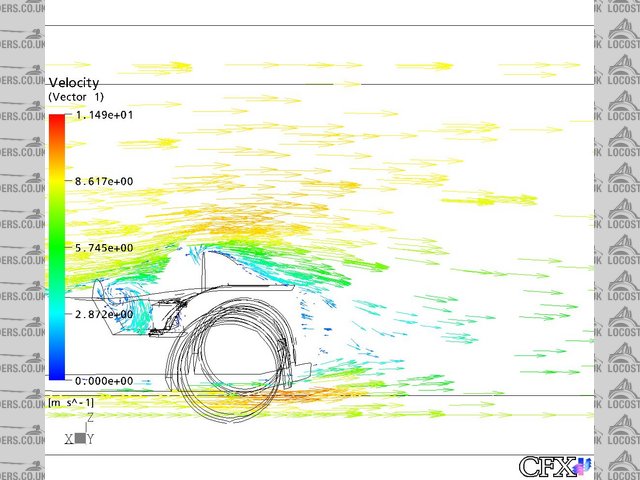
tom_loughlin - 23/4/05 at 08:42 AM
pic 2 -without the bump
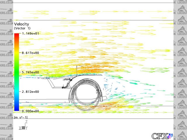
Rescued attachment Mod1Vector2-53.64.jpg
clbarclay - 23/4/05 at 12:54 PM
Does the software just give vetcor diagrams like above, or can it give approximate figures for over all drag coefficient of the car?
tom_loughlin - 27/4/05 at 11:28 AM
it can give drag figures which can sim,mly be converted using the formula:
D=(Cd. A. V^2)/2
where D=drag force
Cd = drag coefficient
A=Max. frontal area
V=flow velocity
in not so sure that the figures i come up with are 100% correct, so im going to hold on before releasing them.
the work im doing now is on pressure distributions and press. coefficient - and im comparing with and without a screen.
heres some pics
this shows the formation of a vortex, between the drivers chest, and the screen.
the streamline shows the path of a particle, chosen from its initial point
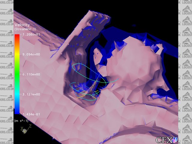
Rescued attachment VorticesCoreScreen6.7-2.jpg
tom_loughlin - 27/4/05 at 11:29 AM
in this pic, we can see the formation of the boundary layer:
i have chosen the extents to be when the boundary layer velocity is 90% of the free stream values

Rescued attachment Mod1BL.jpg
tom_loughlin - 27/4/05 at 11:30 AM
same idea as above, but with the windscreen case

Rescued attachment BLcontour.jpg
colibriman - 27/4/05 at 02:57 PM
fascinating......
just to complicate things a bit....whats the airflow like under the car, especially when the rake is altered....?
tom_loughlin - 27/4/05 at 03:50 PM
how do you mean when altering the rake?
i have tried bringing the neck of the venturi forward, nearer the centreline of the car - to bring the low pressure region nearer the CG, which seems
to work ok.
what im going at the moment is looking at time dependant cases - how vortices change and develop woth respect to time - but it will take a bit of
getting used to!
Tom
marc n - 27/4/05 at 04:57 PM
interesting stuff
like colin said would be interesting to see the air flow below the car at different ride heights
regards
marc
colibriman - 27/4/05 at 07:30 PM
Tom...
As Marc mentioned,
the rake is the angle at which the car ride height sits
e.g. 100mm front & 115mm rear heights from the ground
or maybe 100mm all round
wondering if you can show the differences..
for example if the ride height is higher at the front than the back, in theory this should create lift under the rear of the car...which is really
unwanted..
thanks again for your work.
tom_loughlin - 27/4/05 at 09:45 PM
will have a look at different ride heights - will be interesting to see the effects!
but it will have to wait till exams are done - mid may, then i have some coursework - which i can come up with my own brief for.
thanks for the suggestions guys!
will keep this post updated as and when, but probably wont do an awful lot in the next couple of weeks, as dissertation is in in a week, then exams -
fun!
cheers gents, and if anyone has any more ideas/suggestions/improvements, drop me a line.
Tom
pgpsmith - 27/4/05 at 10:29 PM
Tom,
Can the models can be imported from another software package (i.e. Pro/E or SolidWorks) or as IGES or STEP files? If so, I would be glad to lend a
hand with the modeling if there is work that you want to farm out.
Regards,
Pete Byar
p.s. still puzzled by "an upside down 't' section to neaten the flow round the wheels." (?)
Triton - 28/4/05 at 06:30 AM
Tom,
If i didn't know better i would think you were on acid......drawing pictures like that...
Good luck with the exams.
Mark
tom_loughlin - 28/4/05 at 10:22 AM
Pete, thanks very mich for your offer of help - meshing software works best with solids, but with some tweaking i got my model in from rhino3d in iges
format. as far as i know, *.step and *.igs files work fine, so if you have any existing models you want me to test, i should be able to do them in a
day for you in uni after exams are done.
the way the meshing software works is by represting the actual fluid (in my case, air) as a volume, and the car itself has been subtracted.
by modelling the domain as a cuboid, and boolean subtracting the car model from it, in effect, all you are left with is the air - if that makes any
sense at all!?!
by setting fluid propres, and skin friction etc, the computer pretty much does the rest.
mark, youve got me busted now - doh!!
cheers guys,
Tom
(oops, forgot to explain about the upside 't' - i mean to deflect the air flow from the rotating wheels as mush as possible it will probably
have the same effect as the lips on the front spoiler of an f1 car - do you know what i mean? could also deflect b of air to brakesfor cooling if
needed??)
[Edited on 28/4/05 by tom_loughlin]


