
Simple switch problem .........
RazMan - 22/6/06 at 10:47 AM
......... but is the answer simple?
In my brake fluid res I have a reed float switch which works the wrong way round - the switch closes when there is fluid and opens when the level
drops. This is obviously not good 
The type of fluid switch that I have used is not available in N/O so I need to somehow reverse the switch action with electronics.
What's the simplest way?
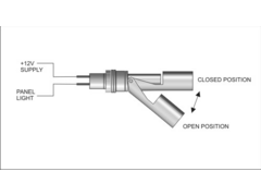
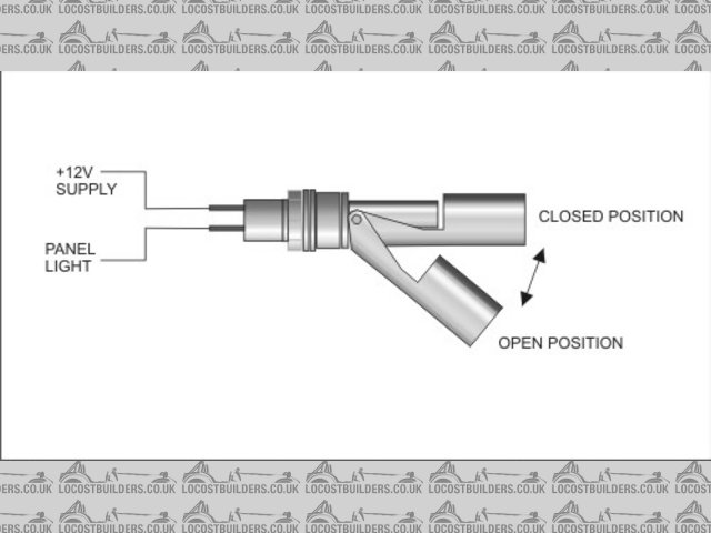
Rescued attachment FLUID SWITCH CIRCUIT.jpg
Just - 22/6/06 at 10:52 AM
12v contactor would do it. These are essentially remote switches which you could wire to switch a live feed through to the light when the live feed
from the reed switch drops. Maplin do them for 240 so probably 12.
RazMan - 22/6/06 at 11:00 AM
I had thought about using a relay and using the n/o contacts but I was hoping to use something solid state - maybe a transistor acting as a switch?.
Bob C - 22/6/06 at 11:17 AM
is there not room to simply turn the switch over?
Bob
RazMan - 22/6/06 at 11:31 AM
Unfortunately the switch only works in a downward arc as shown in the pic. I didn't think about needing n/o contacts when I designed the brake
res so I am stuck with the problem of making the switch work in reverse.
Here's my relay solution but it just seems a bit ott as the panel light is only an led.
[Edited on 22-6-06 by RazMan]
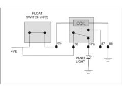
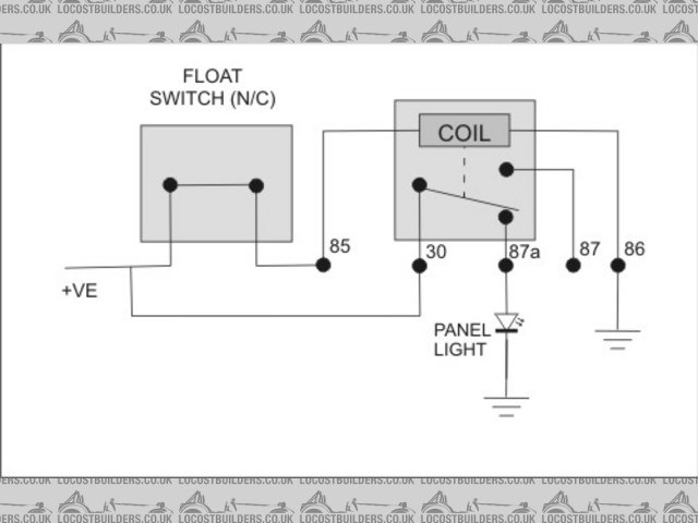
Rescued attachment FLUID SWITCH CIRCUIT 2.jpg
nitram38 - 22/6/06 at 11:37 AM
Sorry to butt in, but doesn't the brake level circuit have to be tested, either by switch or handbrake lever?
Technically your relay would bypass part of the test circuit and thus fail sva. Why not change the cap to a float type? It will have 3 contacts,
common N/o and N/c.
It will also have a membrane that allows you to push the float down and test the circuit.
[Edited on 22/6/2006 by nitram38]
RazMan - 22/6/06 at 11:45 AM
Surely the relay is actually part of the testing circuit isn't it?
I have also got a handbrake switch feeding the panel light too, so if either switch is operated the light will switch on.
nitram38 - 22/6/06 at 11:51 AM
The positive goes to the panel light, then the earth from the panel light goes to the brake float and then to your handbrake.
When the float drops it makes an earth connection, the same as the handbrake, but each time you operate the handbrake your are testing the entire
circuit.
Pressing the cap membrane in checks the float.
Less parts, simpler circuit and a complete test everytime you operate the handbrake. Plus relays can stick.
CorseChris - 22/6/06 at 11:54 AM
You need to have a lamp test function for sure. I have the handbrake warning lamp & low fluid wired to the same lamp.
If all you want to do is drive a (presumably red) LED, try this....
1k resistor, LED, small NPN transistor (say a BC107,8 or 9), 4k7 resistor.
1K from +12 to LED, LED to collector of transistor.
Emitter to ground
4K7 from +12v to base
Switch goes from base to ground.
When switch is closed, base is shorted to ground, LED is off. When switch is open, base gets pulled high, transistor turns on, LED lights. For a test
button (or handbrake warning), you can either put a normally open switch across the collector & emitter, or a normally closed one in series with
your float switch..
...or there are dozens of other ways to do this 
This will work though and should be pretty reliable.
RazMan - 22/6/06 at 12:08 PM
quote:
Originally posted by nitram38
The positive goes to the panel light, then the earth from the panel light goes to the brake float and then to your handbrake.
When the float drops it makes an earth connection, the same as the handbrake, but each time you operate the handbrake your are testing the entire
circuit.
Pressing the cap membrane in checks the float.
Less parts, simpler circuit and a complete test everytime you operate the handbrake. Plus relays can stick.
ermm .... I think you've misunderstood. The float switch is a single pole which opens when the fluid drops (hence my problem)
Or have I missed something?
nitram38 - 22/6/06 at 12:22 PM
Razman, sorry my post was describing the best way to do the circuit with a normal float and the normal setrup. I still think that changing your
resevior cap to a different float and having a normally open circuit is the safest and most reliable way to achieve what you are after.
Relays, transisters etc are just extra failure hazards.
RazMan - 22/6/06 at 01:30 PM
My brake res is a custom made jobbie and therefore I cannot change the cap - if only it was that easy.
CorseChris - your circuit sound more like it - I will have a dig around and see if I can find the components. 
Bob C - 22/6/06 at 04:35 PM
If you are only driving an LED, there will be a resistor in series. Put your float switch across the LED so when the switch closes the juice from the
resistor goes through the switch instead of the LED (so the LED will go out when the switch closes).
et voila.....
Bob
PS I would have thought the switch would be as happy to float upwards as fall down thru gravity, though I could imagine you might need to mount it
lower.....
[Edited on 22/6/06 by Bob C]
RazMan - 22/6/06 at 04:48 PM
quote:
Originally posted by Bob C
If you are only driving an LED, there will be a resistor in series. Put your float switch across the LED so when the switch closes the juice from the
resistor goes through the switch instead of the LED (so the LED will go out when the switch closes).
et voila.....
Bob
PS I would have thought the switch would be as happy to float upwards as fall down thru gravity, though I could imagine you might need to mount it
lower.....
The led has an integral resistor but I see where you are coming from - ingenious
Ref the float going up - you are right when you say it will need to be mounted lower down in the tank. This might actually be the better way to do it
but it unfortunately involves cutting a new hole and welding up the old one. As it is made of 3mm alloy it will have to be tigged and I've only
got a mig 
MikeRJ - 22/6/06 at 05:18 PM
If it's a reed switch then you can usualy invert their operation by placing another permanent magnet close to the switch (you will have to mess
around to find the correct position).
However, if you just want to power an LED when the fluid drops, the easy way is to just connect the switch accross the LED. This means you need to
use an LED with an external current limiting resistor, not one of the 12v LED's with the internal resistor.
Hmm...I started this post at lunchtime and only just posted it, hence repeating what has already been said! You may be able to replace the LED and
use an external resistor. If not a single transistor and a few resistors will do the job.
[Edited on 22/6/06 by MikeRJ]
CorseChris - 23/6/06 at 11:31 AM
I do love the simplicity of using the switch to short out the LED (assuming an external series resistor). Lamp test would just be another normally
closed switch in series with the float I suppose. Fit it on the handbrake and the jobs a good 'un.
I'm trying to remember now if the SVA guy asked me to demonstrate that low fluid made the light come on - I'm sure he must have done as he
was very thorough. I put some float switches in the master cylinder caps but the only way to 'test' them is to undo and lift the cap. Only
much later did I find a source for caps that have a 'proper' switch built in.

