I can get the plug to buzz with a purple arc but it won't fire off the gas. The piezo ignitor in my blowtorch does a much better job with a single white arc. Any thoughts on how I can improve the spark and get the gas to light off?

I am trying to build the igntiion system for my little jet engine. Using a 555 timer as an astable to excited an automotive coil at about 300Hz...
I can get the plug to buzz with a purple arc but it won't fire off the gas. The piezo ignitor in my blowtorch does a much better job with a
single white arc. Any thoughts on how I can improve the spark and get the gas to light off?
reduce the frequency to give the coil more time to charge?
Dave
Prime engine with damp start? Spark will light this which will light gas, jet should then be self sustaining?
What coil charge time are you getting there?
3ms isn't a whole lot of time to charge, trigger, discharge and start again unless you have a good coil and driver.
What's the signal duration you're getting out of your circuit for a single pulse?
[Edited on 24/8/13 by PhillipM]
The issue is lack of energy in the spark to get it to light off the gas in the first place....
I wonder if my coil is knackered...
Looking at it I think I would be better off with a CDI and coil rather than the traditional coil I am using, would negate the back EMF issue I am
having with the switching transitor..
Anyone have a CDI and coilpack kicking about? I only need a single plug though.
quote:
Originally posted by PhillipM
What coil charge time are you getting there?
3ms isn't a whole lot of time to charge, trigger, discharge and start again unless you have a good coil and driver.
What's the signal duration you're getting out of your circuit for a single pulse?
[Edited on 24/8/13 by PhillipM]
quote:
Originally posted by tegwin
Suspect something in my setup is not right. Possibly the coil.... The transistor gets hot too as well which is not ideal
Good point. What's the best way of checking that it is? Measure the voltage across it?
Best way is to stick a scope on there. A volt meter won't tell you much at 300Hz.
Can you post up a diagram of the circuit?
Sadly I don't have a scope. Only a multimeter with a frequency counter on it.
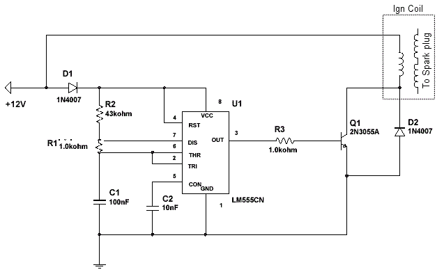
This is the circuit I am using.

The actual astable part seems to work ok as I can measure the expected frequency at pin 3.
If I run with the 1K resistor between pin 3 and the transistor then it doesn't work...
I like the retro transistor 
Not so keen on the circuit though... It might work on a good day, but you really want another gain stage between the 555 and transistor, or a perhaps
a different transistor with a higher gain (a darlington would be better).
Presumably it must still work (to some extent) with the 1k in there as it does spark a bit?
Without redesigning it, I think I'd try lowering the value of the 1k resistor to around 500R to see if that makes any difference.
If I have the 1k in before the tranny it doesn't spark atall. It's removed at the moment. Would it be worth adding a smaller transistor
before the big one do you think? If you can see a better way of doing it I would be so grateful for a sketch
So have you currently got the output of the 555 connected directly to the base of the transistor?
You want some resistance in there or you'll risk damaging the 555 and/or the transistor.
[Edited on 24/8/13 by skov]
[Edited on 24/8/13 by skov]
Have you tried running it at a lower frequency? it does not need to spark at that frequency to ignite so maybe 75 or 100 hz may give time for a
stronger spark output.If the coil drive is the problem then maybe it would be possible to use an ignition amp from a contactless distributor to drive
the coil and feed it the signal from the 555.
Paul
quote:
Why not a glow plug?
Use a piezo from a Calor burner, they light my blow heater, simple to fit and only cost a few quid with no complicated circuits. Ignito r and lead for under a tenner.
quote:
Originally posted by tegwin
Sadly I don't have a scope. Only a multimeter with a frequency counter on it.
This is the circuit I am using.
The actual astable part seems to work ok as I can measure the expected frequency at pin 3.
If I run with the 1K resistor between pin 3 and the transistor then it doesn't work...
Thanks for your thoughts all.
This looks like an interesting product http://www.maplin.co.uk/ignition-amplifier-kit-3162
If I used that I should be able to fire it off with a simple transistor feed from the 555!?
It's the diode across the 2055 that's clamping the fly back and preventing the coil from releasing the charge to the secondary.
Replace the diode with a 1.0mf 250v poly cap.
A 2n3055 has quite a low C E breakdown voltage so no sure how long if will last, plus you need at least 150ma at the base to fully switch it on
assuming the coil is pulling 10amps. Another transistor configured in Darlington pair would help.
A just your 555 to 100hz with mark space of 20% ish to avoid overcharging the coil and frying the 2055.
This sounds like the jet engine would have similar ignition requirements to an exhaust flamer kit such as this one on the bay:
http://www.ebay.co.uk/itm/FLAMER-KIT-FLAME-KIT-EXHAUST-FLAMER-FULL-KIT-/321050177765?pt=UK_CarsParts_Vehicles_CarParts_SM&hash=item4ac014f0e5
And why is there no picture of this jet engine????
Lets see it, what you going to do with it? I'd like a jet engine they sound so cool
My BOE calcs say a 3ms spark is equivalent to a 4 cyl engine doing 10,000 rpm. If you're just trying to light a jet engine, do you need to be banging away that fast? Is the coil charging enough in that time?
Chances are the mixture is wrong and the flash point to high for a simple spark to ignite. A car gets away with it because the compression stroke
heats the air mix up.
You only need a spark every half second or so but it's going to have to be very hot, even then it might need a blast of fresh air to fire up
I'm sure you can hear the spark ticking away on youtube vids of jets starting up, there not very rapid at all
[Edited on 28/8/13 by Mr Whippy]
I had problems with the above circuit years ago and as I know nowt about electronics me and my mate just used a vacuum cleaner on blow and blowtorch
on the outlet, was a bit of a nack trying to get the flame to go back inside past the blades but it worked 
[youtube]http://youtu.be/xXKjUWMiwnc[/youtube]
[Edited on 28/8/13 by Dualist]
Haha.. Yes I had thought about using a blow-torch to light the thing...
But my designs are a little more suffisticated. I intend to have a fully automated digital electronic control (FADEC) unit for a 1 button start and
run..... So I need everything to work properly from the off
The start sequence will involve an electric blower puffing through the combustor to provide air for the ignition and to spool the turbine up. I think
you are right that two or three good quality sparks a second would be more than sufficient.
I don't like the idea of using the transistor as it gets hot and is obviously not the ideal design...I think I need to try something a bit more
inteligent.
Do we think the ignition amp from maplins (link above) would do the job if driven with a small transistor from the 555?
I will post some pics in a week or so once I get things bolted back together. Just at the stage of testing the ignition and fuel systems. once that is
done I can plumb up the lubrication and monitoring systems and see if she will run
quote:
Originally posted by BaileyPerformance
It's the diode across the 2055 that's clamping the fly back and preventing the coil from releasing the charge to the secondary.
.