orton1966
|
| posted on 14/2/11 at 05:09 PM |

|
|
Front Upright Build Log
First all the usual caveats; I make no claim to be an expert, Im not a formally trained engineer, Im just someone who enjoys tinkering with
mechanical things. The following notes on upright design can be commented on, criticised, used for inspiration or discarded out-of-hand. However I
will take no responsibility for other peoples construction, use or fabrication of this or any other similar design. That said I hope there is some
inspiration here for others facing the challenge of making or finding uprights with suitable geometry for their cars.
The story so far, Im building an exo-skeleton type car, inspired by the likes of the Warner R4 and the Arial Atom. Like those and others before Ive
needed to make an early decision on what uprights to use because this dictates suspension geometry, this dictates mounting points, which dictates
where chassis tubes need to go, basically Im really designing the car front the 4 corners and working my way inwards. Decisions so far 15 by 7
wheels, wearing 50 profile tyres, with a dynamic rolling diameter of about 560mm.
I started off assuming Id use something similar to a Haynes roadster of Locost build I.e. Cortina, Sierra or MX5 parts. The first two were discounted
because of perceived short comings in their geometry, the MX5 looked favourable for a while and I even got myself a set to start with. However the
more I tried to finalise the suspension design the more I started to resent the compromise these were imposing on me. Particularly I didnt like the
rack position or the fact the lower wishbone needed to be mounted higher that I would like. Nothing insurmountable but I just figured finding
something else or making my own might be a better option, so I started researching the making option.
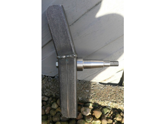
My initial idea was to fabricate something based around a tubular design, a little like the MK produced ones, I figured I could use a simple rear hub
from a small fwd car, possibly even using the same stub axle, turned down to pass through the main tube, see pic below.
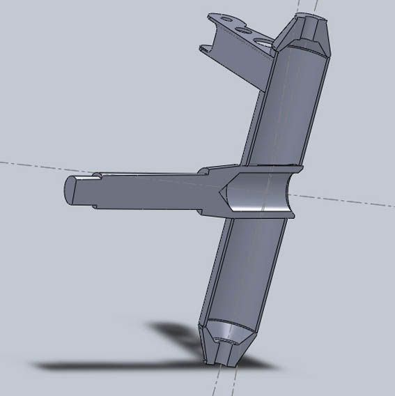
Whist I really like the simplicity of this design it does require several turned parts and I dont have a lathe but that might change soon. Also care
has to be taken welding or brazing the stub axle in otherwise you effect the hardening. If no suitable axle could be found an axle would need
machining again not rocket science but ideally it should be made from something better than regular mild steel bar. Critics would also point-out that
it also has the rose-joint bolts in single-shear however many have successfully made this design work. Anyway whilst researching hubs bearing etc. I
came across this:
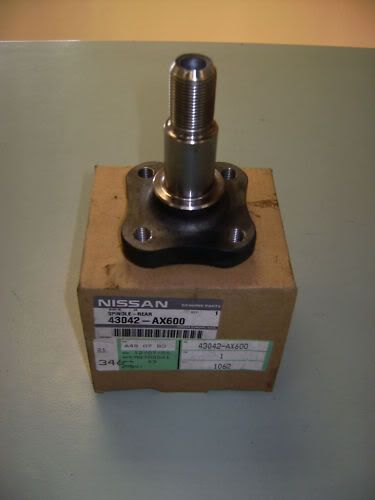
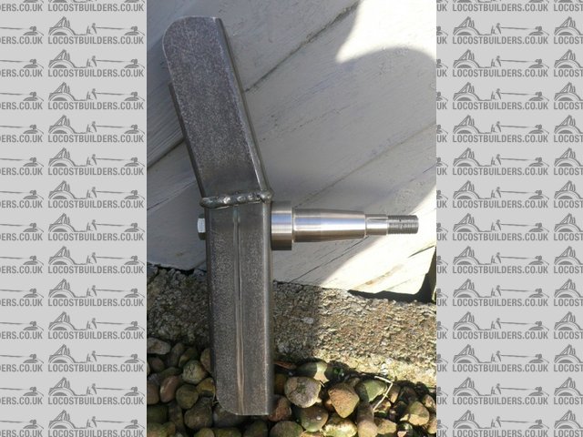
a rear stub axle from a Nissan Micra K12 (about 2003 onwards) There are several things I really like about this part; its short, compact, takes a
equally compact bearing and most invitingly has symmetrical 4 by M10 bolt mountings on a flat square base crying out to be bolted to either a CNC
machined alloy or folded steel type upright.
Whilst I, like many, really like trick CNC stuff and I have got access to CAD to pen a design I dont have easy access to the machining and wanted
something I could play with and tweak without wasting block after block of Alloy. So that eliminated one option, I could have chosen to fabricate
something like the Haynes rears with several cut pieces of plate but I prefer the look of some of the neatly folded parts Ive seen. However again the
reality check was that I didnt have direct access to trick accurate CNC folding equipment so experimentation would again be about paying for repeated
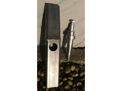
parts to be made. Another option Id seen was based on stock box-section sizes see pic below
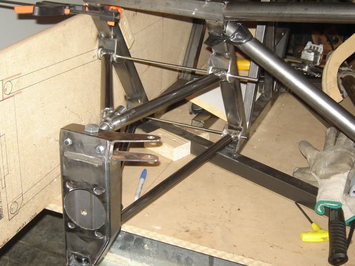
There are several aspects about this design I like and whilst the person behind it cnc milled it all, it equally lends itself to home workshop methods
of cutting and shaping. The conclusion I came to was that although I didnt entirely like the finished design I though the construction technique
could be developed further to give more the look of a folded part and if I could get a suitable sized box-section would be the perfect companion to
the Micra stub axle.
Steel Selection. The micra stub-axle has a square base 68mm across and the PCD of the threaded holes is 65mm meaning it would bolt perfectly to a
piece of 70mm wide box section, rather than mimic the other part Id seen and go for rectangular section I decided square would be better because it
would allow me more flexibility on KPI. I knew 70 by 70mm was widely available with a 3mm wall but hoped to find something a little more delicate,
after much searching I sourced some 2mm ERW, If I wanted to go lighter I could probably find 1.5mm but I figured 2mm would be a good trial size to
test things out.
Basis of the Design: The fundamental objectives of the geometry are minimal scrub, KPI under 8 degrees, caster of 6 degrees, Ackerman steering angles
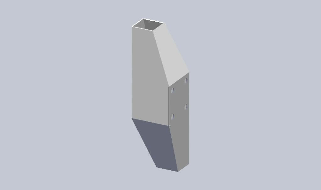
and a distance between top and bottom rose-joint centres of 250mm, time for some metal origami
. Not quite Im still waiting on the elusive 70 x70 x
2mm box which should arrive next week, so for now Ill share the cad pictures of what I intend doing. Like I say I fully expect to tweak things
further as I go.
First cut triangles to allow the box section to fold
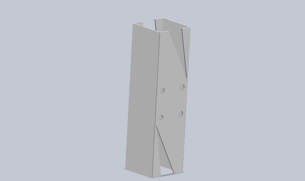
Weld and repeat in the other plane
Then use standard size section to add rose joint brackets and steering arm 50 by 25mm and 50 by 30mm pictured
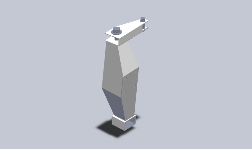 
Anyway more to follow once i've added a hub and brake rotor etc
|
|
|
|
|
interestedparty
|
| posted on 14/2/11 at 05:27 PM |
|
|
This is really interesting stuff, thanks for sharing it and in such detail. Going to have another read through now
quote:
Originally posted by orton1966
Decisions so far 15 by 7 wheels, wearing 50 profile tyres, with a dynamic rolling diameter of about 560mm.
Are you fairly sure of those figures? What actual width of tyre are you using, my calculator gives approx 600 diameter for 195 tyres?
[Edited on 14/2/11 by interestedparty]
As some day it may happen that a victim must be found,
I've got a little list-- I've got a little list
Of society offenders who might well be underground,
And who never would be missed-- who never would be missed!
|
|
|
blakep82
|
| posted on 14/2/11 at 05:44 PM |
|
|
by 'rolling' i'd think he means rolling circumference?
interesting stuff indeed 
________________________
IVA manual link http://www.businesslink.gov.uk/bdotg/action/detail?type=RESOURCES&itemId=1081997083
don't write OT on a new thread title, you're creating the topic, everything you write is very much ON topic!
|
|
|
interestedparty
|
| posted on 14/2/11 at 05:53 PM |
|
|
quote:
Originally posted by blakep82
by 'rolling' i'd think he means rolling circumference?
He did say rolling, although he says diameter whereas the calculators normally give circumference. Easy enough to divide by pi though. Which is what I
did with this calculator which gives rolling circumference
http://www.carbibles.com/tyre_bible_pg4.html
As some day it may happen that a victim must be found,
I've got a little list-- I've got a little list
Of society offenders who might well be underground,
And who never would be missed-- who never would be missed!
|
|
|
Fred W B
|
| posted on 14/2/11 at 06:39 PM |
|
|
Thanks for the post Orton, will follow with interest
Cheers
Fred W B
You can do it quickly. You can do it cheap. You can do it right. Pick any two.
|
|
|
coyoteboy
|
| posted on 14/2/11 at 06:45 PM |
|
|
I'm really interested in the folded steel / micra options, seems like a nice solution. I'm used to looking at billet parts but a bit of
folded steel seems easier and cheaper to say the least. the ones we work with are ~£100 a piece materials only. What's the cost of these
approximately?
Have you done any FEA on the rigidity of it?
[Edited on 14/2/11 by coyoteboy]
|
|
|
orton1966
|
| posted on 14/2/11 at 06:47 PM |
|
|
quote:
Originally posted by interestedparty
quote:
Originally posted by blakep82
by 'rolling' i'd think he means rolling circumference?
He did say rolling, although he says diameter whereas the calculators normally give circumference. Easy enough to divide by pi though. Which is what I
did with this calculator which gives rolling circumference
http://www.carbibles.com/tyre_bible_pg4.html
Found this calculator, http://www.club80-90syncro.co.uk/Syncro_website/TechnicalPages/TRC%20calculator.htm
It allows you to compare different tyre sizes and the effect on effective radius, you'll see you get a variation between static and dynamic
although in theory it should also vary with speed. According to the calculator 15 by 195 by 50 gets 284mm radius or 568mm diameter (dynamic) less
than this if static. So for a start point I chose to start working on 22/560mm as a diameter
Obviously without experience of a given tyre under a given load these are only ever going to be estimates
|
|
|
orton1966
|
| posted on 14/2/11 at 06:51 PM |
|
|
Not yet
quote:
Originally posted by coyoteboy
I'm really interested in the folded steel / micra options, seems like a nice solution. I'm used to looking at billet parts but a bit of
folded steel seems easier and cheaper to say the least. the ones we work with are ~£100 a piece materials only. What's the cost of these
approximately?
Have you done any FEA on the rigidity of it?
[Edited on 14/2/11 by coyoteboy]
Not yet but once I have a finished model I'm happy to let someone have the cad work to give it a go. Although saying that I'm not really
concerned about the rigidity, it's a 70mm cube with a pyramid on each end, it'll be stiff!
|
|
|
Mal
|
| posted on 14/2/11 at 06:55 PM |
|
|
Orton,
That's excellent information.
Are you aware of these, which take your Mirca stub axle a stage further by including a hub and bearings.
VAUXHALL ASTRA MK4 98-04 FRONT WHEEL BEARING 4 HOLE HUB
If you do a search on Ebay you will find pictures of them. They would need a bolt ( a simplification) down the centre to do the job of the drive-shaft
in holding it all together axially.
Mal
|
|
|
coyoteboy
|
| posted on 14/2/11 at 07:13 PM |
|
|
quote:
Not yet but once I have a finished model I'm happy to let someone have the cad work to give it a go. Although saying that I'm not
really concerned about the rigidity, it's a 70mm cube with a pyramid on each end, it'll be stiff!
What's your wall thickness though? 2mm doesnt seem overly thick for the loads on it. That said I suspect many wishbones would deform before any
failure, just stiffening up all round is a good route.
[Edited on 14/2/11 by coyoteboy]
|
|
|
orton1966
|
| posted on 14/2/11 at 07:40 PM |
|
|
quote:
Originally posted by Mal
Are you aware of these, which take your Mirca stub axle a stage further by including a hub and bearings.
VAUXHALL ASTRA MK4 98-04 FRONT WHEEL BEARING 4 HOLE HUB
I was and it was/is still a possibility. The thing with the Micra part is that the base is so close to the size of the box-section almost all loads
are carried into the sides rather than trying to flex the face it's bolted to!
|
|
|
Bare
|
| posted on 14/2/11 at 08:15 PM |
|
|
Interesting experiment.
I'm wondering about the structural integrity of the gizmo though.
It seems likely that stub axle will bend the simple sheet mount plate.. pretty well on the first bump, or worse, corner.
A wee fraction of a mm deformation will result in significant (frightening ?) shifts in the susp geometry.
IF mine i would through bolt the thing and use welded in bushes between the two upright mounting faces.
But then I would prefer to use a shaft type axle, through bolted with a tube bush welded in between the two upright faces.
I'm thinking that stub axle could be better used in a Utility trailer.
|
|
|
orton1966
|
| posted on 14/2/11 at 08:32 PM |
|
|
Brake mounting plate
quote:
Originally posted by Bare
Interesting experiment.
I'm wondering about the structural integrity of the gizmo though.
It seems likely that stub axle will bend the simple sheet mount plate.. pretty well on the first bump, or worse, corner.
A wee fraction of a mm deformation will result in significant (frightening ?) shifts in the susp geometry.
IF mine i would through bolt the thing and use welded in bushes between the two upright mounting faces.
But then I would prefer to use a shaft type axle, through bolted with a tube bush welded in between the two upright faces.
I'm thinking that stub axle could be better used in a Utility trailer.
Crush tubes through the faces are under consideration and I know the rectangular fabricated example in the early pictures features these. Also there
will be a plate bolted between the upright and the hub as part of the calliper mounting meaning the hub is actually bolted through a face of at least
4mm.
I think comparing it to a ulility trailer part is a bit unnecessary, any design is a compromise and plenty use bolt on axles/bearings of some sort,
this one seeks to ensure the loads are carried by a 70mm beam rather than a 2mm (actually 4mm because of the brake mount) plate!
|
|
|
v8kid
|
| posted on 28/2/11 at 05:18 PM |
|
|
Sorry for the late post I've been rebuilding gearboxes Again!
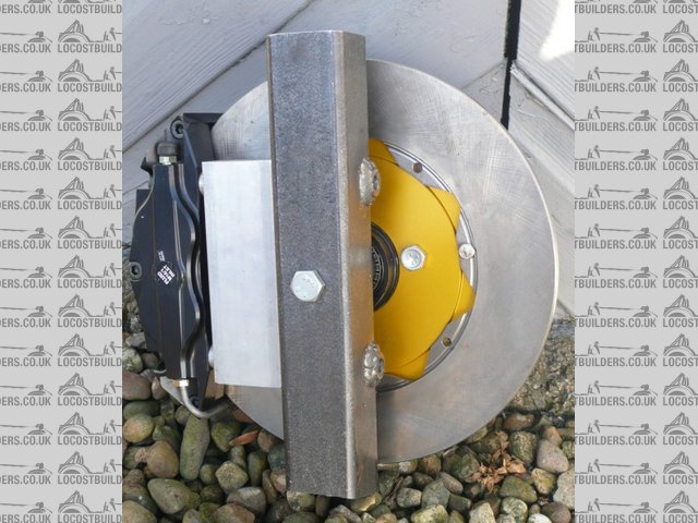
This photo shows my first attempt
high kpi side
You can see that I've use 50mm box section and bolted a stub axle through the upright. The thinking here is to strengthen the upright a bit like
bamboo. Also this axle is much lighter than the bolt on plate pattern.
 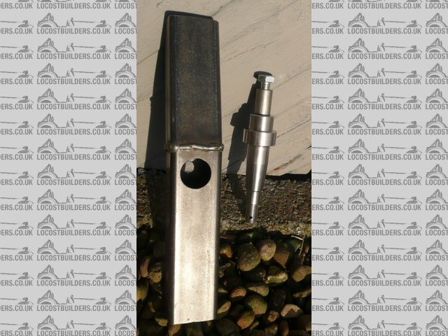
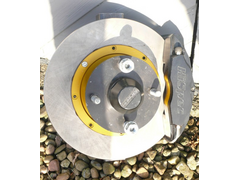
high kpi assembly
here you can see the holes and stub axle. I used a hole saw for the larger hole with a bench drill braced to make sure it was exactly square. The stub
axles are standard cortina bolt in items used by grasstrack racers with a longer bolt and a spacer tube so that it bolts up hard to both faces of the
box section.
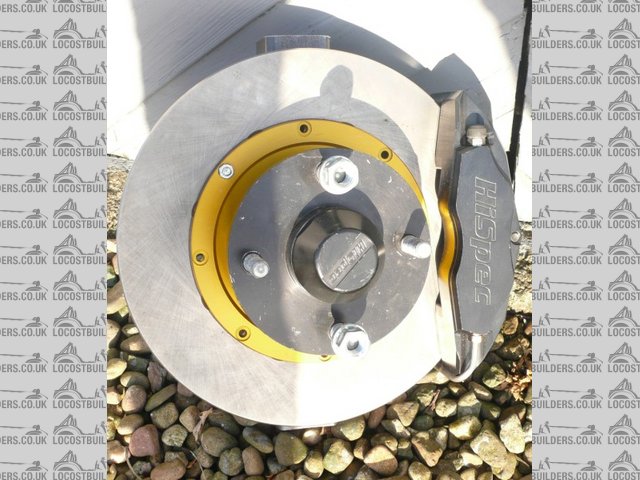
low kpi rear
This version is when I decided to go for a low kpi angle and wanted to see the clearances. You can see the bosses welded on for the calipers on both
sides. The other side will have the steering arm bolted on. Balljoint positions were not drilled as I had not decided on them at that time.
Currently as I am going for a high castor angle the trail would be too high so the next version will incorporate axle lead, a bit like in a bicycle to
reduce the trail to around 15mm.
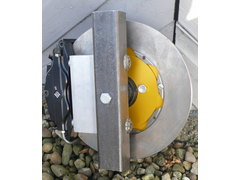
upright front
This is what it looks like from the front and yes the discs are 280mm diameter and they do fit inside 13" rims and yes it was bl00dy
difficult!
Before anyone asks no I have not done a FEA just manual calculations (yup shock horror using a calculator, pen and paper!) principally 'cos my
autocad does not support FEA and I can't find a more up to date version
Cheers!
You'd be surprised how quickly the sales people at B&Q try and assist you after ignoring you for the past 15 minutes when you try and start a
chainsaw
|
|
|
Fred W B
|
| posted on 28/2/11 at 06:52 PM |
|
|
Hi David
I'm always hesitant to make posts like this, but when I have a genuine concern I feel I must.
Are you very sure you have good penetration in the weld at the mid point of the upright? To me the weld profile looks to sit up too much, and looks
like you could have used more heat input. Did you have a bevel prep on the butting edges?
In such a critical component this weld has to be perfect.
Cheers
Fred W B
[Edited on 28/2/11 by Fred W B]
You can do it quickly. You can do it cheap. You can do it right. Pick any two.
|
|
|
v8kid
|
| posted on 1/3/11 at 03:21 AM |
|
|
No probs Fred I appreciate your concern. I think the penetration was OK when I did it I'll check the reverse side again tomorrow to double
check.
Cheers!
You'd be surprised how quickly the sales people at B&Q try and assist you after ignoring you for the past 15 minutes when you try and start a
chainsaw
|
|
|
v8kid
|
| posted on 6/3/11 at 07:38 PM |
|
|
Hi chaps,
I decided to test the upright until it failed. See the separate post today if you want to find out how many g it took! - I'd put a link if I
knew how>
Cheers
You'd be surprised how quickly the sales people at B&Q try and assist you after ignoring you for the past 15 minutes when you try and start a
chainsaw
|
|
|
orton1966
|
| posted on 11/3/11 at 04:35 PM |
|
|
Ready to start
I know I haven't posted much since my initial cad pictures but I now have steal and the other parts so Intend making a start and will be posting
some pic' next week. in the meantime Ive been playing with geometry on cad and I am confident I can get KPi as low as 6 degrees (possibly less)
and still have zero scrub from a regular 37mm offset wheel. For comparison the MX5 needs 11 degrees to get the same centre point steering
|
|
|
v8kid
|
| posted on 11/3/11 at 04:39 PM |
|
|
Are you sure you want zero scrub?
You'd be surprised how quickly the sales people at B&Q try and assist you after ignoring you for the past 15 minutes when you try and start a
chainsaw
|
|
|
andyd
|
| posted on 11/3/11 at 05:12 PM |
|
|
I'm looking to copy the Elise numbers as I don't think anyone will argue that they don't handle/work well.
Previous thread on the subject here.
Andy

|
|
|
v8kid
|
| posted on 11/3/11 at 07:10 PM |
|
|
Good link thanks. But there were loads of arguments both ways there it was far from black and white.
I didn't read zero scrub being a criteria from it in fact I thought it was the opposite but arguable. Quite a few good cars were discussed there
and they were all quite different presumably for different reasons
Cheers
You'd be surprised how quickly the sales people at B&Q try and assist you after ignoring you for the past 15 minutes when you try and start a
chainsaw
|
|
|
orton1966
|
| posted on 11/3/11 at 09:44 PM |
|
|
Scrub
quote:
Originally posted by v8kid
Are you sure you want zero scrub?
I want to have the option of zero scrub with relatively regular wheels but also to be able to use thin wheel spacers to give small degrees of scrub if
I find it doesn't have enough feel. I don't think anyone would say an Elise handles badly, equally an mx5, one has zero scrub the other
does not. My build is more about showing one way to make an upright people can make their own decisions on the geometry. My scrub will be between zero
and about 10mm
|
|
|
v8kid
|
| posted on 12/3/11 at 09:11 AM |
|
|
That is a truly excellent idea!
So what are the variables we want to change? For me it would be scrub, trail,kpi, caster and camber plus of course the vertical height of the
balljoint positions wrt the spindle.
I found it incredably difficult to package my requirements inside a wheel and ended uf getting split rim wheels so I could bury the stuff deep enough
to get a low kpi.
I suspect it is this practical aspect of packaging which determines the geometry in production cars. As locosters we can do things manufacturers
cannot even that superp car the elise.
For example my split rim wheels were refurbished and assembled from bits over 3 eBay purchaces and the tyres cost 99p!
Manufacturers would be prevented from doing this due to cost and ruggedness and I feel we should leverage advantages like these.
Don't get me wrong I have no illusions I can get anywhere near the superb elise in any respect but I can have some fun and learn something at
the same time.
Cheers! and congratulations on the design work
You'd be surprised how quickly the sales people at B&Q try and assist you after ignoring you for the past 15 minutes when you try and start a
chainsaw
|
|
|