b14wrc
|
 posted on 30/5/12 at 11:36 AM posted on 30/5/12 at 11:36 AM |

|
|
Steel choice - is this overkill?
Hi All,
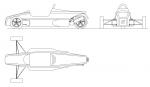
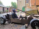
I have a question regarding tube choice, I am nearly at the stage (2 years of design already!!) where I can finally get rid of my wooden frame a lot
of you may have seen, and actually start making the car in steel.
I am optimising the design now for final steel ordering, im looking at strength/stiffness, safety, cost and weight.
I could go down the line of making it all from 25mm x 25mm x 1.6mm box, however have looked at using the format below.
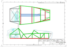 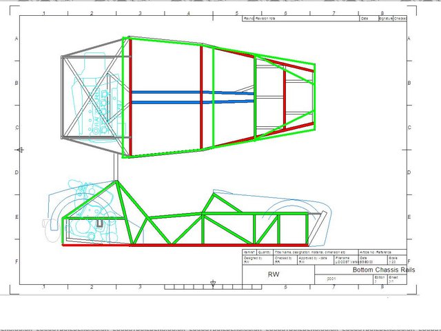
Steel Choice
Red = 25mm x 25mm x 2.0mm
Blue = 19mm x 19mm x 1.6mm
Green = 25mm x25mm x 1.6mm
Does this sound reasonable? The extra tubing thickness should add strength, remember Im using a Fiat coupe 20v turbo motor
..
All comments welcome, really trying to decide if this is overkill and the 1.6mm wall thickness will be adequate? Cost wise there isnt much in it.
Regards, Rob
20vt powered rear engined locost
|
|
|
|
|
rost
|
| posted on 30/5/12 at 11:49 AM |
|
|
What grade of steel are you going to use? You could use regular S235 for the green tubes and S355 for the red tubes, both in 1.6mm thickness. S355 is
50% stronger than S235.
Charlie don't surf!
|
|
|
motorcycle_mayhem
|
| posted on 30/5/12 at 11:51 AM |
|
|
Everyday car? your steel choice doesn't seem incorrect to me.
Featherweight moped-powered racing Westfields use(d) 18 gauge, everything with a proper engine was 16 gauge. Known issues around certain critical
areas, *even* with the 16 gauge (engine mounting area and diff area). The crash-fantastic Westfield Euro chassis is something else...
Unless you're after the last kilo for competion (and) you're not a 17 stone lump of lard, what you've proposed looks fine to me.
|
|
|
Slimy38
|
| posted on 30/5/12 at 12:19 PM |
|
|
I have no idea about structural advantages, the only thing I might say is perhaps add up the lengths of each type of steel and see if it divides well
by 6 metres. If one of the colours adds up to 6.1 metres (or 12.1 metres, 18.1 etc) then you might have a fair bit of wasted metal. Although that may
not be a bad thing?
And don't get the two 25mm ones mixed up, your chassis may inherit some very odd characteristics if you accidentally weld a 2mm piece on one
side and a 1.6mm on the other! 
|
|
|
Alan B
|
| posted on 30/5/12 at 12:50 PM |
|
|
quote:
Originally posted by rost
What grade of steel are you going to use? You could use regular S235 for the green tubes and S355 for the red tubes, both in 1.6mm thickness. S355 is
50% stronger than S235.
Maybe, but surely you are designing for delflection and stiffness in which case all steels are pretty much the same.
Just IMO
|
|
|
designer
|
| posted on 30/5/12 at 01:07 PM |
|
|
Don't try to be too technical, the same dimension material makes construction easier and mild steel is as good as anything for what we do.
A frame is, as a says, a single unit and does not need thicker tubing in certain places.
The use of thicker tubing in places only comes in effect when making a chassis like my trike will have; eventually!
|
|
|
rost
|
| posted on 30/5/12 at 01:37 PM |
|
|
quote:
Originally posted by Alan B
quote:
Originally posted by rost
What grade of steel are you going to use? You could use regular S235 for the green tubes and S355 for the red tubes, both in 1.6mm thickness. S355 is
50% stronger than S235.
Maybe, but surely you are designing for delflection and stiffness in which case all steels are pretty much the same.
Just IMO
How I read the OP it is a strength v. weight concern. The difference in Polar inertia between a 25x25x2 and a 25x25x1.6 tube is around 15%, so
stiffness would not be harmed that much.
Charlie don't surf!
|
|
|
designer
|
| posted on 30/5/12 at 03:16 PM |
|
|
quote:
The difference in Polar inertia between a 25x25x2 and a 25x25x1.6 tube is around 15%,
Getting too technical!
Polar inertia is caused by weight overhanging the wheelbase and your design does not have much chassis doing that.
15% of what? I presume 15% is the weight difference between the two tubes.
|
|
|
britishtrident
|
| posted on 30/5/12 at 03:24 PM |
|
|
1.6mm is easier to cut than either 2mm or 1.2mm -- 2mm is plain hard work and 1.2mm is more difficult to cut smoothly even with a finer tooth
blade.
1.6 is also a good choice for MIG welding with 1.6mm it is very easy to get full penetration but harder to blow holes in than 1.2.
[I] What use our work, Bennet, if we cannot care for those we love? .
― From BBC TV/Amazon's Ripper Street.
[/I]
|
|
|
hughpinder
|
| posted on 30/5/12 at 04:07 PM |
|
|
Wot he said ^^^^
I find it easier to weld together (properly) tubes of the same thickness. I believe you would get a more rigid chassis by using 32*32*1.6 box in place
of the 25*25*2, while retaining the same weight.
Regards
Hugh
|
|
|
MRLuke
|
| posted on 30/5/12 at 04:16 PM |
|
|
quote:
Originally posted by hughpinder
I believe you would get a more rigid chassis by using 32*32*1.6 box in place of the 25*25*2, while retaining the same weight.
Regards
Hugh
This was going to be my comment also. Also makes it harder to mix up your box section
|
|
|
b14wrc
|
| posted on 30/5/12 at 04:26 PM |
|
|
Hello Chaps,
Some very decent comments there thanks all. Steel wise, I was just going for standard mild steel, really which ever metals for you sell. I
havn't done much in the way of calcs as the chassis is very similar to the book design. Obviously the engines now in the back. I'm just
conscious that my motor is a bit heavier than most.... And as it's in the back I may get more bending/twisting through the chassis.
Alternativly, I could add additional diagonals and keep it all at 1.6mm?
The general feeling is tubes of the same thinkness weld better?
I was planning 19mm box on the internals as it saves me a little space, on the inside of the car....and I think it woul look a bit neater, the tunnel
will be left un panelled.
Yer, I've been dividing by 6000mm on it all, trying to get it as economical as possible. 
Rob
20vt powered rear engined locost
|
|
|
b14wrc
|
| posted on 30/5/12 at 04:35 PM |
|
|
1 1/4" box is slightly more expensive, but would get a better 2nd moment of area value for similar weight, so I'd expect the chassis to be
stiffer....
This seams to me as a decent bit of evolution of a well tried design. Many others opted to use 32mm box on the lower chassis rails?
Think i'll plot some graphs..... I like taking my time and planning it.... That's why after 2 years my car is still made out of wood!
Lol
Rob
20vt powered rear engined locost
|
|
|
iank
|
| posted on 30/5/12 at 06:25 PM |
|
|
Larger section same gauge is much stiffer. iirc 50x50 is about 8 times stiffer than 25x25 for the same thickness, but obviously only 2x the
weight.
Tiger used to make their frames from 30x30.
--
Never argue with an idiot. They drag you down to their level, then beat you with experience.
Anonymous
|
|
|
britishtrident
|
| posted on 30/5/12 at 06:35 PM |
|
|
quote:
Originally posted by b14wrc
1 1/4" box is slightly more expensive, but would get a better 2nd moment of area value for similar weight, so I'd expect the chassis to be
stiffer....
This seams to me as a decent bit of evolution of a well tried design. Many others opted to use 32mm box on the lower chassis rails?
Think i'll plot some graphs..... I like taking my time and planning it.... That's why after 2 years my car is still made out of wood!
Lol
Rob
Actually the upper chassis members rather than the lower rails would benefit from more stiffness, the upper rails generally are the ones that resist
higher compressive loads. Tensile loads generally aren't a problem in a space frame but any member loaded under compression is prone to
Euler Buckling. This is a particular problem with long unsupported rails such as the cockpit sides and engine bay.
[I] What use our work, Bennet, if we cannot care for those we love? .
― From BBC TV/Amazon's Ripper Street.
[/I]
|
|
|
rachaeljf
|
| posted on 30/5/12 at 07:46 PM |
|
|
The second moment of area (generally denoted "I" ) of the individual members in a "triangulated" space frame has almost no
effect on the overall bending or torsional stiffness of a space frame.
If you are putting any loads into the chassis within the span of a chassis member then the *bending* capacity of that chassis member does matter, and
its I value comes into play. For instance, if your chassis has an engine mount attached halfway between two chassis node points, a larger/heavier
engine would warrant a larger "I" for that member to cope with the higher bending loads being imposed.
Cheers R
|
|
|
britishtrident
|
| posted on 31/5/12 at 11:36 AM |
|
|
quote:
Originally posted by rachaeljf
The second moment of area (generally denoted "I" ) of the individual members in a "triangulated" space frame has almost no
effect on the overall bending or torsional stiffness of a space frame.
If you are putting any loads into the chassis within the span of a chassis member then the *bending* capacity of that chassis member does matter, and
its I value comes into play. For instance, if your chassis has an engine mount attached halfway between two chassis node points, a larger/heavier
engine would warrant a larger "I" for that member to cope with the higher bending loads being imposed.
Cheers R
All members in compression even in a true space frame are Euler Struts, with a member in tension the value of I of the member dosen't
matter but with a long thin member in compression the I value and length of the member is a a major consideration. This is why modern
racing car space frames are composed of many much smaller triangulated sections than in the early days of Formula Ford. An easy way to look at
is consider a length of piano wire, very strong and stiff in tension but unable to take any load in compression.
http://www.nottingham.ac.uk/~evzjso/Teaching/SAD/Pin_ended_strut.html
As a real world example early Lola 342 chassis suffered badly from lack of stiffness until somebody spotted that the top rails of the
chassis were buckling under load. The chassis was rebuilt with top tubes with a section which had a greater I value and the car started
getting results.
[I] What use our work, Bennet, if we cannot care for those we love? .
― From BBC TV/Amazon's Ripper Street.
[/I]
|
|
|
rachaeljf
|
| posted on 31/5/12 at 02:02 PM |
|
|
Thanks for the link b-t, but as I mentor other structural engineers I'm already pretty familiar with structural analysis!
I was trying to keep things simple for the benefit of non-engineers.
Don't confuse stiffness with ultimate capacity.
An ideal space frame will suffer total collapse if just one member fails, which could be in tension or compression. "Buckling" of a strut
is considered failure as the geometry change is irretrievable.
With the Lotus chassis, the "lack of stiffness" was due to second order, "p-delta" geometrical effects, which suggests poor
geometry! In other words, the designer used a compression member with excessive slenderness, which was probably visibly bowing. If the offending
member had actually buckled they would certainly have a stiffness problem as the chassis would have folded up. The excessive bowing could have been
"fixed" by either using a member with a greater I if the circumstances forced them to use a very long compression member (e.g. engine bay
sides), or by adding further bracing to reduce its effective length (which leads to your mention of "smaller triangles".
Yes, the magnitude of the undesireable deflection does depend on the strut's I value and to use your own analogy, it is bad form to make a space
frame out of piano wire.
So, I'll repeat but with more words: Provided the frame does not suffer poor geometry, and your frame is operating within the normal region of
serviceability, the I values of individual members have only a very tiny effect on the frame's global stiffness. If you design an
ill-conditioned frame, where p-delta effects are significant then yes the I values of the excessively bowed members are important. However, you should
not be designing a chassis that is in danger of folding in two if you place your mug of tea on it.
Cheers R
|
|
|
Alan B
|
| posted on 31/5/12 at 02:14 PM |
|
|
Rachael,
For my own piece of mind do you agree with what I said earlier...
"Maybe, but surely you are designing for deflection and stiffness in which case all steels are pretty much the same. "
This was in response to an alternate material spec. suggestion.
Thanks,
Alan
|
|
|
Paul_C
|
| posted on 31/5/12 at 02:26 PM |
|
|
I think that the only way to know what are suitable choices bar building and testing is to perform some analysis.
I have used the LISA finite analysis program on the spaceframe design shown in Racing and Sports Car Chassis Design by Michael Costin and David
Phipps, Appendix 1, because it is fully dimensioned, fuly triangulated hence solvable and has the front suspension mounts at spaceframe nodes. From
memory it isn't too difficult to do by entering the x, y and z coordinates along with the tube cross sectional areas and Youngs modulus. Once
the loads were calculated I then used a spreadsheet to calculate the Euler cripling loads and safety margins.
It's difficult to determine what realistic loads are though and also what stiffness is required.
|
|
|
rost
|
| posted on 31/5/12 at 02:51 PM |
|
|
quote:
Originally posted by Alan B
Rachael,
For my own piece of mind do you agree with what I said earlier...
"Maybe, but surely you are designing for deflection and stiffness in which case all steels are pretty much the same. "
This was in response to an alternate material spec. suggestion.
Thanks,
Alan
I do agree with you too, the E-Modulus is the same for different steel alloys. I understood that the OP wanted the thicker tubes for strength and
picking a slightly better material would achieve the same thing.
Being dutch, I don't know all of the proper terms in English, so might make some errors there 
Charlie don't surf!
|
|
|
Alan B
|
| posted on 31/5/12 at 02:58 PM |
|
|
Rost,
I agree the higher spec. material would be "stronger"......just not any "stiffer". I know the OP asked about
"strength" and your answer was valid.
My point was that we should design for stiffness in spaceframes.
Again, just IMO
|
|
|
rost
|
| posted on 31/5/12 at 03:06 PM |
|
|
That's what I said . The E-Modulus stays the same, so it won't be any stiffer. For instance: deflection of a
beam with a single support is dependent on the E-Modulus and Polar
Inertia. The Polar inertia comes from the tube's sizing and the E-modulus does not change between steel grades. Changing steel grade does not
make any difference, changing the tube's sizing will.
With FEA the Polar Inertia doesn't have an impact on node deflection (the joints between the different tubes), it does matter if you apply a
force on the tube itself, instead of the node.
[Edited on 31/5/12 by rost]
Charlie don't surf!
|
|
|
rachaeljf
|
| posted on 31/5/12 at 03:47 PM |
|
|
quote:
Originally posted by Alan B
Rachael,
For my own piece of mind do you agree with what I said earlier...
"Maybe, but surely you are designing for deflection and stiffness in which case all steels are pretty much the same. "
This was in response to an alternate material spec. suggestion.
Thanks,
Alan
Yes Alan, different steels are all pretty much similar for Young's Modulus, 200-205GPa or thereabouts.
Cheers R
|
|
|
Peteff
|
| posted on 1/6/12 at 04:12 PM |
|
|
Keep it simple and use the same stuff throughout if you can and basically yes it is overkill and might also be confusing.
yours, Pete
I went into the RSPCA office the other day. It was so small you could hardly swing a cat in there.
|
|
|