Padstar
|
| posted on 14/10/13 at 12:47 PM |

|
|
Haynes Rear Sus Bracket set up
After some advise on the rear set up of my Haynes Roadster MX5 brackets before i fully weld.
As there is no jig to install these and adjusters on the lower arm i assume they allow for a bit of play. This said having tacked the lower brackets
into place, i seem to need a lot of adjustment on the movement bolts to get the hubs sitting plumb? How much will they level out when the car is
dropped on the wheels as maybe i am over extending the adjustment bolts? - Does that make sense.
If my current set up is correct and this much adjustment is required would i be best in inserting a steel "packer" behind the lower
brackets so that the arm is moved outwards without the us eof extending the bolts?
My second issue is how much play does the top bracket allow. I can obviously adjuste either of the bolts to move the hub in/out at the bottom and
in/out left or right but i think this may put strain on the upper bracket. Any advise in how to set up correctly / what poijts to measure from etc to
ensure that i have a good base before i fully weld.
Was so excitting to see a hub hanging from the back but i just feel it is wrong as is and will cause problems.
Almost looked like an F1 car without its boots on!!
|
|
|
|
|
skov
|
| posted on 14/10/13 at 05:55 PM |
|
|
Is it a Saturn MX5 build?
If so, I have to wind my adjusters out futher than I'd like to get the rear hubs sitting at a sensible angle.
I think the rear lower wishbones should have been designed a bit longer...
Packing the lower brackets out sounds like a good alternitive if you already have the wishbones though.
|
|
|
Padstar
|
| posted on 14/10/13 at 06:08 PM |
|
|
Rear suspension is of Saturn design and the adjusters currently have to be wound out quite a distance and one that I am not entirely happy with. It
certainly wouldnt allow for further outward adjustment should it be required after completion. I think I will pack out. What angle should the hub sit
at when the car is off the ground? Any ideas?
|
|
|
skov
|
| posted on 14/10/13 at 10:08 PM |
|
|
I'm not entirely thrilled by how much I've got my adjusters wound out...
This is what I had to set them to to get about 1 degree of negative camber:

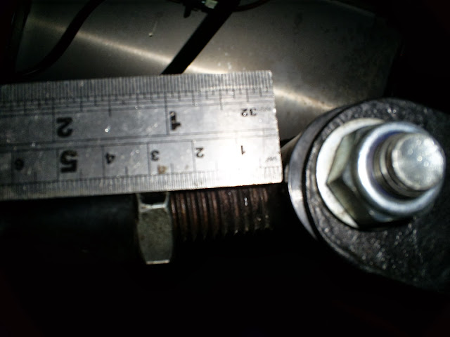
Don't know what what angle the hub sits at when the car is off the ground, but the lower wishbones should be horizontal, or pointing down
slightly when it's sitting at a normal ride height.
|
|
|
Padstar
|
| posted on 15/10/13 at 05:37 AM |
|
|
Mine will be of a very similar distance if left unaltered. Given this would you recomemd inserting a section of 15mm box behind the bracket. Strange
that they'll seem to be so far out?
If the lower bone is to be level or pointing down at ride position i am guessing slipping down somewhat when on stands.
|
|
|
Slimy38
|
| posted on 15/10/13 at 07:09 AM |
|
|
I've had a bit of a look at the rear suspension, and I'm still not convinced it'll go together as it's meant to. I think the
problem for me is that there are key measurements missing from the plans, so depending on whether you go for scratch built wishbones or prepackaged
you might have to modify the chassis to suit. You should also consider that you still have to have the correct dimensions to reuse the driveshafts and
diff, although 15mm out is only 7.5mm (ish) at the driveshafts so it should be ok.
Personally I was going to get the diff mounted inside it's frame, put the brackets in the right place but then build the wishbones from scratch.
If I work on the premise that the lower wishbones should rest horizontally, the driveshafts are a fixed length and the uprights are 1 degree in I
believe I should be able to calculate the length of upper and lower wishbones.
|
|
|
bill132hotrod
|
| posted on 16/10/13 at 12:16 PM |
|
|
Suspension
If you are not happy there is an easy way round it. Weld the nut or two to the tube ( put two nuts on your threaded bit and screw into tube tack weld
into place, remove threaded bit and weld nuts fully , then re tap thread. this way you will gain at least 19 mm on the tube and save yourself a lot of
time .
then just add a new locking.
But don't forget to run a tap down the thread after to ensure there is no binding.
[Edited on 16/10/13 by bill132hotrod]
[Edited on 16/10/13 by bill132hotrod]
PERSEVERANCE is the word of the week. Stick with it the results are SWEET.
|
|
|
Padstar
|
| posted on 4/11/13 at 01:40 PM |
|
|
I spent the weekend fixing the diff, drive shafts, bones and rear hubs into place to the previously tac welded brackets and its all over the place.
Not only are the adjuster bolts extended to far for my liking but the drive shafts elevate outwards towards the hubs which i am sure is incorrect.
I plan to strip down next weekend and start from fresh using the following method of make it fit as built rather than from the questionable and
limited dims available. Any thoughts on this would be much appreciated;
1) Install top wishbone brackets at the recomended dimension to both sides
2) Insert a piece of 25mm x 50mm box section on its side to teh lower bracket rail cut arround any uprights that interupt. I hope this will give a
more substantial and sound fixing that the smaller rail there currently and will bring the brackets out to reduce the requirements of excesive
adjuster extension.
3) Hang hub front upper bracket and install drive shafts.
4) Plumb hubs straight with drive shafts leveled.
5) Tac weld lower brackets in place.
I think this way will mimic a close road position of when the car is dropped roughly level shafts and plumb hubs. With this in place i think the
adjusters will still have enough play in them to tweek when the thing is rolling.
Does that make sense and seem logical or am i going way of track with this?
It was my first real weekedn in the garage this week since the "summer" started and i am keen to get back into it over the winter months.
Seing the rear come on was a great motivator.
|
|
|
Padstar
|
| posted on 29/12/13 at 06:50 PM |
|
|
I have just finished installing the rear brackets. Not yet fully welded as my mig has been playing games.
I ended up adding a a 40x40 box section onto the chasis where the brackets go. This made the bracket fitting far better with minor inward adjustment
available and lots of out adjustment available on the lower bones. I am far more comfortable with this option even if it is adding weight. Any reason
why it is a bad move before i fully weld tomorrow?
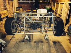 
Rear View
Rear View with wheels installed for effect
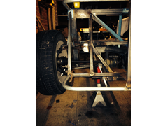 
Rear Sus Bracket Packer
40x40 box section more visible
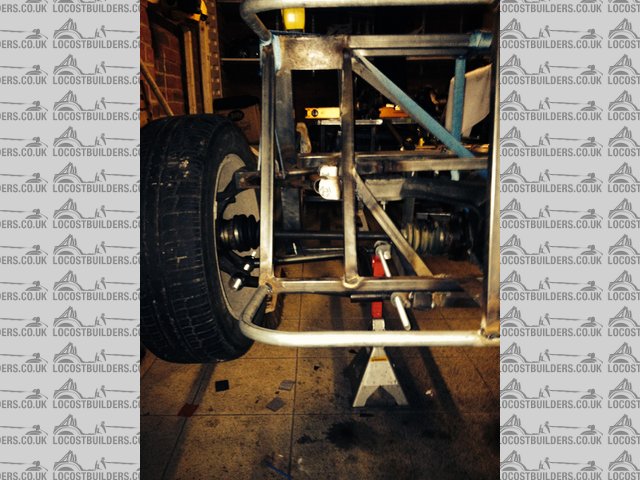
I have levelled the brackets with the diff in place using the shafts as guidance for location. As you can see the safts are now relatively level with
the rear hubs. I can then set up accurately when the car is dropped on the floor with the shocks and camber adjusters on the bones. Sound correct?
|
|
|


