43655
|
| posted on 29/12/13 at 05:09 PM |

|
|
Mid Engine Chassis
Right i know this isn't anything like the average locost, well it sure hasn't been low cost so far either!
But i've had to take a break from building the chassis having had to redesign it.
Nothing minor but the engine wouldn't fit 
Will probably be fitting a 2.7t V6 (longitudinally still) but they're big buggers...
I digress, here's what i have at the moment, any comments would be welcome


|
|
|
|
|
coozer
|
| posted on 29/12/13 at 06:18 PM |
|
|
Whats the V6 out of? Trans?
I've been thinking of something just like that using an Audi V6 or V8..
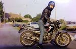
1972 V8 Jago
1980 Z750
|
|
|
v8kid
|
| posted on 29/12/13 at 07:06 PM |
|
|
Good luck with getting the engine in and out I made the rear cross frame bolted on mine but it is a nuscance taking it on and off. In the same vein
is there room for the headers without splitting them? I ended up with 2 headers each side but that was for a v8 I guess a v6 will be easier I made the rear cross frame bolted on mine but it is a nuscance taking it on and off. In the same vein
is there room for the headers without splitting them? I ended up with 2 headers each side but that was for a v8 I guess a v6 will be easier
Where will the rear suspension springs mount?
You usually only need one diagonal e.g. on the roll hoop, and at the front subframe.
Have you tried some of the free FEA they are really easy to use all you need is a day to familiarise yourself.
Have you worked our the front/rear weight balance? The problem with using tintop gearboxes is the gearbox extends well behind the output driveshafts
with a consequential rearwards weight balance. Mine worked out at 35/65 and I lift the front wheels clear of the deck in second - not good!
Cheers!
You'd be surprised how quickly the sales people at B&Q try and assist you after ignoring you for the past 15 minutes when you try and start a
chainsaw
|
|
|
43655
|
| posted on 29/12/13 at 07:45 PM |
|
|
audi, 2.7 bi-turbo, although failing that it'll be a commoner's 1.8t
Trans will be whatever it comes with, but yeah they do stick out a fair way
inline-5 diesel engine wit the audi gearbox

ha ha yeah i was going to make the big cross a bolt-in affair
engine clearance is a concern, the v6 is a really wide engine! so there may have to be more bodgery, but i do't really have any inspiration

I've not been able to use FEA, solidworks will only do single parts.
Any particular software you would recommend then?
Not yet modelled the rear suspension, but it will be pushrod, probably with the shocks mounted to a tube going over the gearbox.
the two diagonals used to be more structural, but also from a safety aspect
Also I did have a proper tunnel modelled, d'you think i need it, from a structural point of view?
leaning towards yes, but it's really small inside, and all tubework etc from front to rear can be simply run through the sideskirts (about
200x300mm)
|
|
|
ceebmoj
|
| posted on 29/12/13 at 08:13 PM |
|
|
As you have gone to the trouble, of mounting one of the rod ends at the front in what I am informed is the correct orientation and the brackets look
like that are laser / water jet cut it looks relatively easy with a couple of extra parts for all of the joints to be mounted in this orientation.
Also when using rod ends rather than packing to fit exactly between the two sides of the bracket if you cut the top hole over sized to fit the spacer
not the bolt you can change the location of the rod end by just packing the bottom spacer.
 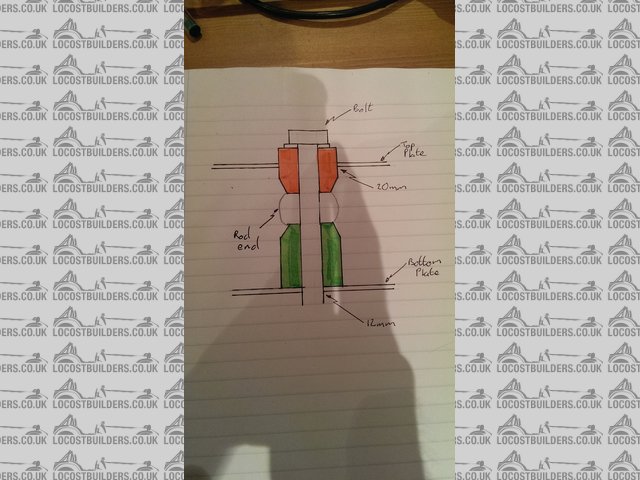
Description
Sorry for the pants sketch but is shows what i'm trying to say
|
|
|
43655
|
| posted on 29/12/13 at 09:43 PM |
|
|
ah but becuase the rear rod end is located in the fore/aft direction, any adjustment in the rod ends will move the front rod end along the shoulder
bolt.
I don't understand 'correct' mountings, i've heard one way is right, i've heard the other way is right. Only diference
is clearance, as far as i can tell the contact area is always the same... *sigh*
|
|
|
ceebmoj
|
| posted on 29/12/13 at 10:54 PM |
|
|
I said 'correct' because of a
Formula student article there have
been some posts on hear that have become heated on the subject. However this one seams
reasonably balanced. My next car will have them mounted the wrong way,
so that I can achieve the articulation I want.
I think the car looks good (what are you doing for body work), but as you are designing from scratch it might be worth seeing if you can mount the
joints the other way as you seam to already have the required articulation.
[Edited on 29/12/13 by ceebmoj]
|
|
|
Nosey
|
| posted on 29/12/13 at 11:37 PM |
|
|
Is it a road car? Bodywork? I haven't the tech knowledge to comment on suspension etc but though the gearbox overhang is long I think
there's something very cool about being able to see the end of a gearbox casing low under the body work, kinda Porsche 917 style.
A tidy rear end!
|
|
|
43655
|
| posted on 31/12/13 at 02:10 PM |
|
|
suspension is a nightmare some very valid stuff there as far as designing an ideal setup.
The body is actually a bastardised VW Caddy pickup, group-b-esque arches to 1.8m wide. Fibreglassed one-piece front, bumper, whole rear end etc. most
of it will have be custom done.
But yeah having a lonng gearbox is not a problem at all as far as space goes, the overhang from wheel centreline to the end of the body is the best
part of a metre
There sure is, although it won't be as low as i'd like, running 17's the 'box has to be fairly high compared to the chassis
which is unfortunate.
Oh and yes, road car hopefully with some trackdays and such
|
|
|
PhillipM
|
| posted on 2/1/14 at 06:26 PM |
|
|
That is only the 'right' way to mount rod ends if they're in line with the forces - I.E. The same angle as the main tubes - when
they're mounted on little stub tubes like that you're bringing bending load into the equation, which negates all that.
|
|
|
Doctor Derek Doctors
|
| posted on 2/1/14 at 07:37 PM |
|
|
I'd have a serious think about your pedal box. If you have integral mast cylinders it's going to be stuck way into the cabin to avoid them
poking far into the wheel well. Also you don't have any mounting points. If you want to use hanging pedals you have a tube right where it needs
to be. Also running a steering column through there could be difficult.
If you've got the CAD capability model everything (even if only roughly) as place takers, it's really easy to forget something and then
have no space when you come to build. It's worth signing up for GrabCAD and 3D content central as there are most of the standard and off the
shelf bits already on there, even if they aren't exactly what you plan to use they save the space and populate the assembly.
Designer and Supplier of the T89 Designs - Single Seater Locost. Build you own Single Seater Racecar for ~£5k.
Plans and Drawings available, U2U or e-mail for details.
Available Now: The Sports Racer Add-On pack, Build a full bodied Sports Racer for Trackdays, Sprints and Racing.
www.t89.co.uk
www.racecarwings.co.uk
callan@t89.co.uk
|
NOTE:This user is registered as a LocostBuilders trader and may offer commercial services to other users
|
43655
|
| posted on 22/1/14 at 08:15 PM |
|
|
Got much better understanding of 'correct' wishbones now, thanks.
Have been racking my brain trying to make a correct mounting method.
What i have is simple and effective, although will be a pain in the arse to make!
Took the advise of modelling as much as possible. currently got steering mostly sorted with an extended escort rack, and upright pickup points. just
got to think about Ackerman now.
Chassis model in Iges format (from Solidworks) https://grabcad.com/library/tube-chassis-caddy-v4-4-1
Can view it in 3D on the site too
or

Any comments so far?
Rear half will be getting cut apart again to make space for the enormous 30v 2.7tt V6, and better suspesion set up
That said, what's the best type of suspension? Semi-trailing like the Ford GT is nice but looks complicated to set up, or just stock with double
wishbone? similar set up as the front?
|
|
|
43655
|
| posted on 28/1/14 at 08:34 PM |
|
|
Nothing...?
|
|
|
ceebmoj
|
| posted on 28/1/14 at 10:12 PM |
|
|
Can you post some more pictures showing the pedal box and frount suspention?
|
|
|
43655
|
| posted on 29/1/14 at 08:40 PM |
|
|
not done the pedal box area yet, once I'm happy with the uprights I'll move onto that
Screenshot once solidworks has done with updating to 2014
|
|
|
Doctor Derek Doctors
|
| posted on 29/1/14 at 08:49 PM |
|
|
quote:
Originally posted by 43655
Nothing...?
Don't take this reply as harsh, it's just me imparting some experience in a to the point manner.
I think you have two issues
1) you've started at the wrong end, you're designing a the chassis and then trying to fit existing parts into it. The chassis is something
that holds everything together so you should lay everything out and then 'join the dots' with the chassis. You already have an engine and
body decided so a lot of decision is already made.
2) you need to have an ultimate idea of what sort of build you want? Simplest? Cheapest? Fastest? Best Looking? Is it for road? Track? Race? You ask
what rear suspension is best but only you can answer that based on what you want to achieve. If you want cheap/simple/robust then the original Audi
front suspension, hubs and driveshafts mounted on a fabricated sub-frame would probably be best way to go, whereas if it's ultimate speed then
some sort of bespoke double wishbone/inboard damper set-up would be best.
A robust part numbering system is useful, a large assembly like that can easily get out of control, if you want a pre created one PM me and I can send
one over. Also if you want any modelled parts I already have a decent library so may have what you need.
I'm currently designing a scratch build car myself and the fist two months have been spent deciding what I want to do, gathering data and
modelling the pre-determined parts. I have a near complete layout of mechanical parts and components. The chassis is now just starting to take shape
around that.
I'd love to see yours finished as the caddy is a cool motor, I was more of a Jetta man myself and always wanted to build a mid engined mk2 using
an Audi I5 Turbo.
Designer and Supplier of the T89 Designs - Single Seater Locost. Build you own Single Seater Racecar for ~£5k.
Plans and Drawings available, U2U or e-mail for details.
Available Now: The Sports Racer Add-On pack, Build a full bodied Sports Racer for Trackdays, Sprints and Racing.
www.t89.co.uk
www.racecarwings.co.uk
callan@t89.co.uk
|
NOTE:This user is registered as a LocostBuilders trader and may offer commercial services to other users
|
Sam_68
|
| posted on 29/1/14 at 09:58 PM |
|
|
quote:
Originally posted by 43655
Nothing...?
As with Doctor Derek, please don't see the following as intentionally critical, but since you asked for comments  : :
1) I agree with Ceebmoj; more detail of the pedal box and front suspension would be helpful to understand the design.
2) I agree with V8kid - getting the engine in past the crossbracing on the first pics would be very, very tricky. Do we take it from their omission on
the latest pic that you've decided to go with a removable crossbrace (sensible)?
3) The front bay appears to lack triangulation to the top, bottom and sides?
4) The rear bulkhead, at the back of the engine bay, is not triangulated and will be prone to lozenging. Maybe some sort of diaphragm bulkhead with
the tail of the gearbox built into it? (as Doctor Derek says, the function of the chassis is to join the dots, and the dots your rear bulkhead needs
to join are the mounting bolts just behind the driveshaft on the gearbox).
5) The cockpit sides are not properly triangulated; the tubes form a quadrilateral toward the rear.
6) The scuttle bulkhead is not fully triangulated - this is where we could do with more detail of the pedal box.
7) Is there any potential to triangulate the 'roof' of the roll cage?
8) The base of the chassis is untriangulated. Are you intending a stressed panel for the undertray, and if so, what material... I'd be wanting
to see a fairly decent thickness of aluminium honeycomb panel, if there is to be no tubular triangulation of this area.
9) the angled front legs of the 'transmission tunnel' framing meet the lower tubes of the front suspension bay in the middle of a tube.
Would it be possible to angle these slightly further back so that they meet to form a node point at the base of the inner vertical tube on the scuttle
bulkhead? Then extend the rear pickup for the lower rear wishbone rearward to locate on the same node point, rather than in the middle of the tube as
it is at present?
10) You're showing housings for spherical bearings on both upper and lower front wishbones at the moment. Does this mean you're designing
an upright that allows for camber adjustment by shims? If not, then the upper wishbone will need to be designed to accommodate a rod end or
ball joint, rather than a spherical bearing, to allow for camber adjustment? You could screw the Rose joints in and out on the chassis pickups, I
suppose, but it'd be a ball-ache getting everything equalised without upsetting the caster.
11) In response to your earlier question: a proper tunnel would add substantially to the stiffness. Do you need it? Who knows - how stiff is stiff
enough? You've a big, powerful engine, though, so I'd be tempted to go for it, yes.
12) Have you modelled the front suspension motion ratios yet? Just visually, the dampers don't appear to offer all that much bump travel, once
you've taken into account bump rubbers and the rocker ratio?
13) Reiterating Doctor D's (very important) comment about joining the dots, you tell us that you haven't modelled the rear
suspension yet, but getting front and rear suspension geometry (and hence roll axis... I have an obsession about fixing roll centre locations so that
the roll axis doesn't move around and upset dynamic weight transfer as the suspension deflects) fixed would be my first step. Only once
you know where the front and rear suspension pickups are can you try to join the dots between them with a properly triangulated structure of tubes.
Me and Doctor D disagree about Jettas, mind you - I had a Mk. 2 Jetta as a kid that tried to kill me by going into a tankslapper on a fast bend, so
I've fallen out with them!
Best of luck with your project, though!
|
|
|
43655
|
| posted on 29/1/14 at 10:40 PM |
|
|
yup definitely. I have done everything about as back to front as possible. if doig this was the original intention then i would have taken the time to
design it and stick to it, but it's constantly been changed revised and updated. I started the chassis, then decided I wanted to get a twin
turbo V6 instead of an inline 4 so pretty much the whole rear needs re-doing.
I'm not sure what you mean though, the wishbones, uprights just about everything is custom for this project.
I guess I want fairly simple, but i want adjustability, and pretty reliable. So using rod ends on the inners, which will have the rubber covers,
outers will be S13 ball joints in theory. hubs are A6/S4 bolt-on's double-drilled for 5x114 (Speedline 17x8 wheels)
Certainly build speed isn't a rush it's taken long enough already! I'm a design engineer by day, so laser cutting, machining, TIG
welding etc are all do-able But I've spent a lot of time trying to get the best engineered solution, for example the wishbones with the
inline rod eds and ball joints, even though it makes the chassis side awkward!
Spent a bit of tie and the GT40's rear suspension had me interested, having the trailing links on the bulkhead and the interesting layout
appealed. but will stick with double wishbone. Just wondering what sort of setup it should have in comparison to the front. All i know is a slightly
higher roll centre is a good idea. Static camber not really necessary and a bit less camber gain than the front at a guess?
In regards the part numbering, I know what you mean as I do it I work. Getting by for now, just got to archive all my old models!
What sort of cad models do you have then? I've been using GrabCad for anything i can, and it's been fairly useful. steering rack and
calipers so far
Sam_68, reply pending tomorrow! That's a lot, thank you all so far
[Edited on 29/1/14 by 43655]
|
|
|
43655
|
| posted on 30/1/14 at 10:32 PM |
|
|
yeah i think the bracing will go, even if it would have made it a lot stiffer. it will be alright.
they would have been removable though.
Front end shouldn't be too hard, although i can't triangulate between the rear mounts on the firewall as the fuel tank will sit in there.
Not sure how stiff it should be made in the front-to-rear direction in the hopefully unlikely event of a head-on collision. I'll definitely take
the advise though.
Considering simplifying the front end considerable with regular bushes and parallel wishbone mounts - aka standard locost fashion. I'm not a fan
of poly-bushes though.
With regards the rear end, the gearbox will be sticking out by a foot or so, 'box depending. So can't run anything through it, and
extending the chassis all the way behind the box seemed counter-productive.
Must admit that was an attempt at making it a bit easier to get in, it's going to be incredibly cramped!
Will see how the pedal box stuff shapes out for the triangulation there, but suspect.
Again roof, I could but considering it's usage (95% road probably) I wasn't sure how necessary it would be. Or from a rigidity point of
view?
Wishbones were rod-end adjust but as above, i think i'll go down the much simpler route of bushes, and yeah perhaps shim adjusted outs, not sure
yet. Would rather have solid welded mounts to be honest, but i do want to have adjustability in the suspension...
Updated model with a tunnel. yeah I can see it being beneficial for rigidity, although it doesn't really 'end' anywhere, and the
front isn't much better yet. Will have to think about it
Nope not got there yet. I modelled up the suspension as sown earlier in the thread, but i've not yet decided on pushrod & rocker, or just
running the shocks down to the wishbones
How can you have a fixed roll centre then? surely it moves about with roll and bump. I've been using Vsusp to layout the suspension, and eyeing
it up on Solidworks. Mind you the Vsusp 'model' is pretty out of date.
I should really get an engine and gearbox to at least get rough models off before doing any more, but really can't afford the ~£750 for a FWD
01E box and an engine yet.
Anyway thanks for that too, I've done some more reworking to the model. Again will get some more images we I'm happy enough with it
[Edited on 30/1/14 by 43655]
|
|
|
PhillipM
|
| posted on 30/1/14 at 10:45 PM |
|
|
The rear stays/diagonal and the roof are very important for rigidity, they're what makes the upper structure transfer load properly.
|
|
|
Sam_68
|
| posted on 30/1/14 at 11:21 PM |
|
|
quote:
Originally posted by 43655yeah i think the bracing will go, even if it would have made it a lot stiffer. it will be alright.
they would have been removable though.
If you use reamed (ie close tolerance) bolts, you needn't lose too much stiffness with a bolted-in rear crossbrace.
Edited to add: and yes, as PhillipM has just said, above, omitting the rear cross-brace altogether is not a sensible option - you'd lose
far too much stiffness in the rear structure. I think that a bolt-in brace is the only sensible way to go.
quote:
Originally posted by 43655With regards the rear end, the gearbox will be sticking out by a foot or so, 'box depending. So
can't run anything through it, and extending the chassis all the way behind the box seemed counter-productive.
You wouldn't need to extend the chassis all the way behind the box - in fact you wouldn't want to.
As I tried to explain before, the rear bulkhead needs to line through with the mountings just to the rear of the driveshafts.
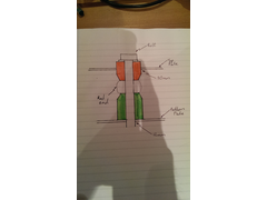
Apologies for the crap sketch, but I can't be arsed breaking out the CAD at this time of night:
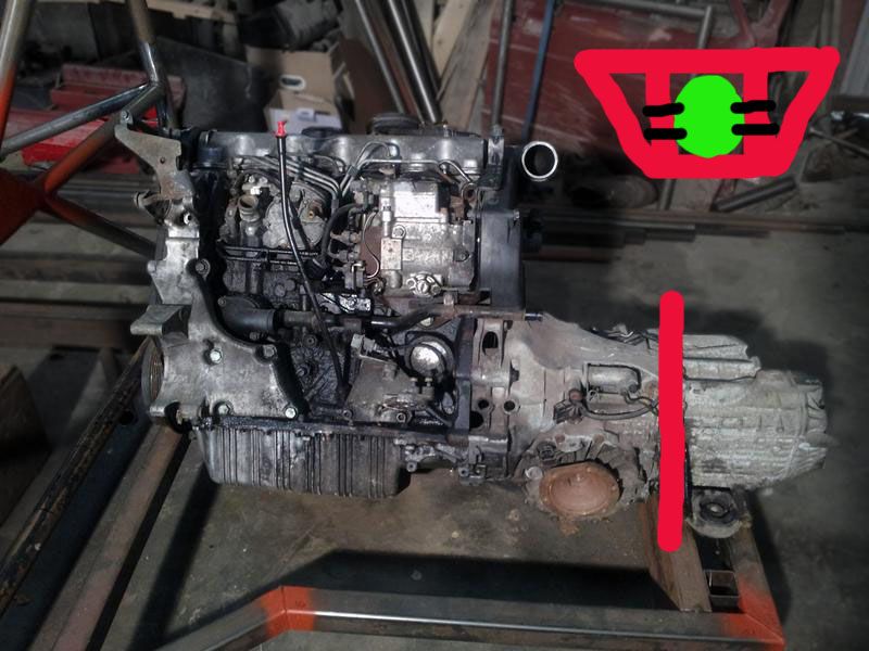
The red line I've drawn on the gearbox shows where the rear bulkhead (hence the end of the chassis) needs to be. The tail of the gearbox would
run though the bulkhead, not the other way round!
The little diagram at the top right is the b/h drawn from the rear: the red would be the tubular frame, the green blob the gearbox casing running
through it (which could then form a stressed part of the b/h, once it's bolted in place, depending on whether you are prepared to tolerate the
NVH of a rigidly mounted drivetrain), and the black lines the mounting bolts for the gearbox.
This bulkhead would also take the rear pickups for the wishbones ...once you've calculated their lateral positions, of course! Obviously, you
ideally want the pickups to be at each corner of the bulkhead (at the 'node points' ), rather than somewhere in the middle of a tube,
which is why you need to design the suspension first, then design the spaceframe to join them up - it's back to Dr Derek Doctor's Dot to
Dot!
quote:
Originally posted by 43655How can you have a fixed roll centre then? surely it moves about with roll and bump. I've been
using Vsusp to layout the suspension, and eyeing it up on Solidworks. Mind you the Vsusp 'model' is pretty out of date.
With care and effort, is the short answer!
If you don't try, roll centre location on double wishbone set-ups can be quite poor. If you make the effort, it can be very good.
I'm not familiar with Vsusp, but I've just had a very quick glance at it, and while it does at least plot the roll centre movement as you
move the suspension around, it would seem to be a matter of trial and error arriving at suspension pickup positions that keep the RC well constrained.
I use SusProg3D, which allows you to give the program certain parameters to work to, such as limiting the roll centre movement to a certain amount,
keep the camber change within certain limits, etc. It will then automatically calculate all the possible pickup positions that meet the parameters you
have set. It still takes a certain amount of trial and error (and as with all computer programs, it's just a tool - it has its limitations and
'garbage in = garbage out' ).
SusProg3D also allows you to program pushrod linkages to work out motion ratios, damper open and closed lengths, etc, which is helpful if you're
planning a pushrod set-up. It does cost a few hundred quid (still cheap compared to the more sophisticated packages that I wish I could justify the
expense of...), but it's a big step up from the free 'gadgets' like VSusp.
...but the bottom line is that it is possible to come up with a double wishbone design that keeps roll centre movement down to a few
millimetres for the full range of suspension movement, if you're careful. It's not something that the professionals shout about, but trust
me, they usually go to a lot of trouble to ensure that roll centres are very well located indeed.
What you're trying to achieve is roll centres at both ends of the car that are pretty much fixed (within a few millimetres) relative to the
sprung mass, for the full range of normal suspension movement.
... Or you can take the coward's way out and use a deDion with a Watts or Woblink for lateral location, in which case the roll centre is
basically fixed by the chassis pivot bolt on the linkage.
[Edited on 30/1/14 by Sam_68]
|
|
|
Sam_68
|
| posted on 31/1/14 at 12:04 AM |
|
|
quote:
Originally posted by 43655
There sure is, although it won't be as low as i'd like,running 17's the 'box has to be fairly high compared to the chassis
which is unfortunate.
I've just picked up on this comment, too.
Obviously it's a matter for personal judgement, and a lot of angularity on the driveshafts is a bad thing, but perhaps not as bad as lifting the
entire mass of the engine and gearbox higher in the chassis, to allow you to run the driveshafts straight!
As a starting point, I'd be drawing in the engine/gearbox as low as you can to give sufficient ground clearance under the sump (say 100mm for
road use; possible as little as 75mm if you want to push your luck - I've run 'Sevens' this low and never had any problems), then
work out what angle the driveshafts are. If the driveshaft angles are too steep (IIRC about 7degrees angle in the static position is the normal
recommended maximum, then check that the angle at full bump/droop does not exceed manufacturer recommendations for the CV joints), then lift the
engine and gearbox just enough to make them acceptable and no more!!
You do not want the biggest mass in the car sitting any higher than it absolutely has to!!
|
|
|
PhillipM
|
| posted on 31/1/14 at 12:25 AM |
|
|
Or work like hell to use longer shafts or use CV's that'll cope with more angle...
|
|
|
ettore bugatti
|
| posted on 1/2/14 at 03:06 PM |
|
|
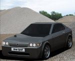
http://www.goldendust.cz/wp-content/gallery/spyker-c8-spyder/resize-of-flower_open.jpg
Maybe usefull to determine the engine height/location, but the Spyker isn't top notch in the handling department.
|
|
|
43655
|
| posted on 2/2/14 at 09:20 PM |
|
|
Would probably use shoulder bolts, and reamed housings as you say.
Was hoping to ditch the brace but you're right, it would add a bunch of rigidity. Will put it back in the model.
Te driveshaft/gearbox thing is a bummer but at least with a 90 degree vee engine weight should be lower than an upright engine anyway. I'll be
removing all the useless crap off it, turbo's are low down already so it's a good start.
I think i mocked it up once with straight driveshafts and it's not that high, but i certainly won't need a dry sump!
not very accurate, but it won't be that awful

Naturally if i can get away with lowering it i will, that's an 012 box i think, the 01E I'm after is longer and thinner. hopefully
doesn't have the outputs lower.
Sam_68, that's how it is in the recent-er models, i am trying to get the whole dot-to-dot of the nodes worked out. Doubt i'll be solid
mounting gearbox or engine though.
I'm having a crack at the roll centre thing, which way should it be constrained, up/down or laterally?
you say relative to the sprung mass, i can only vaguely guess at how that will be laid out. From what i've read elsewhere it sounds as though
the roll centre should be pretty close to the centre of mass. Yet i've also see cars set with roll centres just above the ground. I don't
know...
I've used solidworks to work out pushrod ratios pretty successfully. It's a little trial-and-error but it's also 'free'!
|
|
|