gav2612
|
| posted on 24/12/15 at 05:28 PM |

|
|
How much movement room round the gearbox in the transmission tunnel?
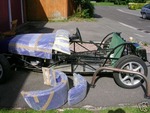
Now cracking on with rebuilding my sylva striker crossflow to duratec. I'm using a mk3 Mx5 gearbox which bolts straight up to the duratec 2.0
engine. To get it all to fit however, I'm mounting the gearbox further back than the old type 9 was. After moving the chassis uprights at the
entry to the tunnel, I've got the gearbox to pretty well back where it needs to be. The bellhousing is however pretty well jammed in with only 1
or 2 mm side to side and up and down movement as its sitting tight to the drivers and passengers footwell. I'm rubber mounting the engine and
box so just wondering if this will be an issue with not allowing much twisting or movement of the drivetrain?
|
|
|
|
|
mark chandler
|
| posted on 24/12/15 at 05:49 PM |
|
|
You will be amazed how much they move about, 5mm minimum IMHO
|
|
|
garyt
|
| posted on 24/12/15 at 05:54 PM |
|
|
I would think you would need quite a bit more clearance than 1 -2mm as the engine WILL rock quite a bit more than that, if you can replace the rubber
with polyurethane and as little as possible you could probably half the movement but I would still be aiming for a min @5 - 10mm clearance , sorry
remember we are not mad just creatively insane !!!!!
|
|
|
Smoking Frog
|
| posted on 24/12/15 at 06:02 PM |
|
|
I worked to 10mm clearance, maybe you could get away with less. But 1-2mm is not enough.
|
|
|
big_wasa
|
| posted on 24/12/15 at 06:30 PM |
|
|
I worked on 10mm min and that was with super stiff engine mounts.
|
|
|
ian locostzx9rc2
|
| posted on 24/12/15 at 06:59 PM |
|
|
As everyone 10mm but 15mm would be better they move around a lot more than you think even with h/duty mounts .
|
|
|
madteg
|
| posted on 24/12/15 at 07:35 PM |
|
|
I had a knock every now and again when going around right hand corners, been there since i built the car. When i fitted long ratio box found the top
end of box had been hitting chassis upright. I had 10mm clearance, i now have 15mm and no knocking. Kev
|
|
|
gav2612
|
| posted on 24/12/15 at 08:36 PM |
|
|
Thanks for all the feedback, I was hoping against hope that you weren't going to come back with the answers you did, but was expecting it!
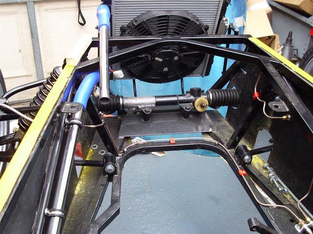
My other option is to modify the front chassis rail which is fouling on the sump at the front hence wanting to push the gearbox back as far. I only
need approx 30mm to move the bellhousing far enough forward to give the required clearance round the transmission tunnel. The link below shows the
picture of the chassis rail that is catching with black tape on it. The newer Raw chassis has a different set up with the suspension mount in the same
place but triangulated from there forward rather than straight across as per the part with the tape on. you can just see that in the bare frame
picture in the link. My thoughts were to either follow the newer raw design, or simply cut out the part, move it forward 30mm and weld it back in.
The latter would be the easiest option Thoughts on how this would affect the chassis strength?
http://s482.photobucket.com/user/Gav2612/story
[Edited on 24/12/15 by gav2612]
|
|
|
garyt
|
| posted on 24/12/15 at 09:17 PM |
|
|
hi I cant open the link but from what your describe, the reason the cross tube is there is to transmit the wishbone forces through the mount, then
the side rail and thus through said tube, shortening it and moving it forward disrupts this flow of forces , your side rail effectively becoming
unbraced just where it needs it.
Angling the tube forward (triangulating it) is not as good as it is now, but is the best compromise as the outer end is still opposite the wishbone
mount so does brace / transmit the wishbone loads, so if this would give you the room needed to move the engine / box forward then imo it is the best
compromise and answer to your clearance problems
remember we are not mad just creatively insane !!!!!
|
|
|
40inches
|
| posted on 24/12/15 at 09:28 PM |
|
|
MK did this;
Coolant pipe fixing
|
|
|
gav2612
|
| posted on 24/12/15 at 09:57 PM |
|
|
Thanks again guys. Struggling to work out how to upload photos to the site, although I think my photo bucket post above should now be working
Very frustrating for the sake of 25 or 30mm, but it looks like I'll need to start over with the design Around the suspension mounts then. The
old sylva chassis was designed for the crossflow which is a very short engine, the newer raw chassis was designed for the zetec which is similar in
length to the duratec I'm fitting hence the difference in design I presume. The mk Indy set up looks really good, but maybe a bit complicated.
It looks like I'd be best cutting out the crossmember then and triangulating forward from the mount. I presume as shallow an angle as possible
to clear the sump would be preferable to help spread the load. Very much learning as I go here, have spent many years tinkering with cars that big
companies spent millions designing, so just cutting bits out here and welding new bits in is very different. It's kinda fun, like a big mecano
set! Merry Christmas when it comes
|
|
|
loggyboy
|
| posted on 24/12/15 at 10:08 PM |
|
|
I can only assume the duratec and mazda box combo needs to sit alot further forward than the zetec and type 9 - or the sylva chass differs alot from
the current Raw one as i had reasonable space to the front of the engine. Left right in tunnel eas tight though.

Mistral Motorsport
|
|
|
garyt
|
| posted on 24/12/15 at 10:10 PM |
|
|
the thing to remember is that the forces are using the front wishbone mount as a fulcrum so yes a shallow angle is best however this would end up as
an X frame , so you could move your cross tube forward and then triangulate from the rear wishbone position to the cross tube as said before it is a
compromise between ideal and practical if I can be of any help just shout.
I see your in fife a wee bit south of lossiemouth  but there's a lad building a Haynes about 10 mins from cowdenbeath might be handy to
compare notes or even a visit and a cuppa if interested / local but there's a lad building a Haynes about 10 mins from cowdenbeath might be handy to
compare notes or even a visit and a cuppa if interested / local
remember we are not mad just creatively insane !!!!!
|
|
|
gav2612
|
| posted on 24/12/15 at 10:51 PM |
|
|
Thanks For the offer of help Gary, my parents stay just outside Cowdenbeath and I'm only 10 mins away so may give you a shout for his number
Loggyboy- yes the raw set up you have shows the angle forward from the rear lower suspension mounts. Mine just runs from mount to mount square across
the chassis so would hit the front of your engine at the pulleys. The front of the bellhousing on the mx5 box is now sitting about 50mm back from
where the type 9 one did, it's purely the difference in the length of the engine. The 1700 crossflow that came out of it was tiny.
|
|
|
loggyboy
|
| posted on 25/12/15 at 08:20 AM |
|
|
quote:
Originally posted by gav2612
Thanks For the offer of help Gary, my parents stay just outside Cowdenbeath and I'm only 10 mins away so may give you a shout for his number
Loggyboy- yes the raw set up you have shows the angle forward from the rear lower suspension mounts. Mine just runs from mount to mount square across
the chassis so would hit the front of your engine at the pulleys. The front of the bellhousing on the mx5 box is now sitting about 50mm back from
where the type 9 one did, it's purely the difference in the length of the engine. The 1700 crossflow that came out of it was tiny.
More like this..?

As you mention, adapting the chassis to suit the modern design is probably the best option.
[Edited on 25-12-15 by loggyboy]
Mistral Motorsport
|
|
|
gav2612
|
| posted on 25/12/15 at 09:33 AM |
|
|
That's exactly it loggyboy. I don't need a huge amount more room, but changing it to similar to your newer raw design would give
what's required. Out with the angle grinder again once Christmas is over!
|
|
|
gav2612
|
| posted on 27/12/15 at 09:36 AM |
|
|
Finally logged on with a PC rather than ipad, so ive managed to upload photos.
picture 1 of the chassis as is. The sump is hitting where the black tape is.
[img]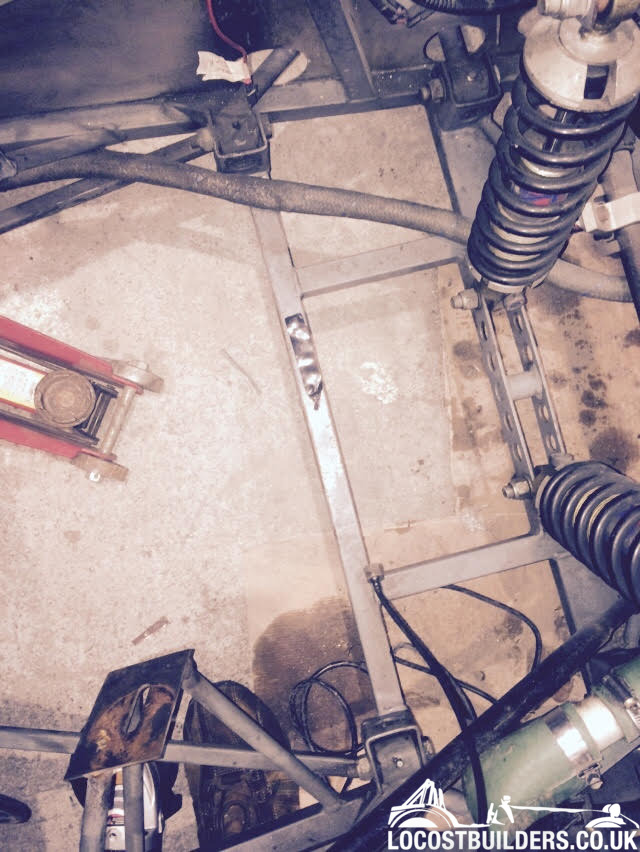 [/img] [/img]
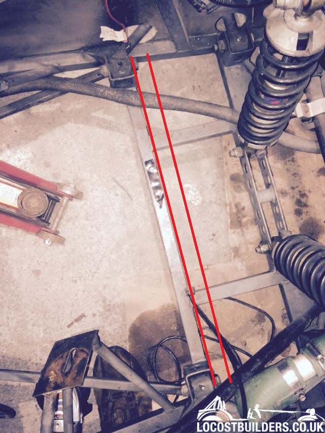
I only need 20 or 30mm extra to space the gearbox so option 1 was to cut the crossmember out and re weld in front of the lower suspension points. it
would still be welded to the front of the suspension points so would tie them together as well as joining the two outer chassis rails
If i'm going with the more modern Raw style design and that would also give me a lot more room to move the engine and box back and forward to
suit, does it matter where I weld on to? See angles below in options 2 & 3. Thanks for all your help again guys.
Option 2
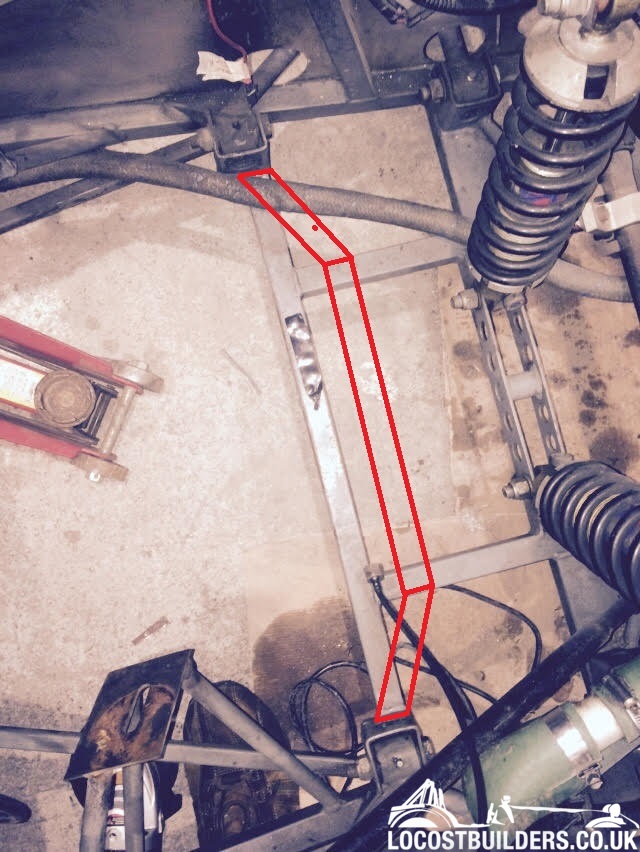
Option 3:

|
|
|
Smoking Frog
|
| posted on 27/12/15 at 10:18 AM |
|
|
I would go for option 1. Easy to do, closest to original design.
|
|
|
loggyboy
|
| posted on 27/12/15 at 10:32 AM |
|
|
Definitely 2 or 3 IMO, keeps the reinforcement directly on the wishbone joint. If you ever plan to sell or adapt the car further 3 would give greatest
future options.
Mistral Motorsport
|
|
|
gav2612
|
| posted on 27/12/15 at 10:54 AM |
|
|
I was leaning towards 2 or 3 anyway just because it gives me a bit more room to play with when fitting the engine. Anyone with more engineering
knowledge than me like to comment on whether welding as per 2 or as per 3 would give the best support or indeed any other way that would be better?
Thank God I found this forum, or I really would be shooting in the dark!
The more I look at it, option 2 would give the support to the inside of the wishbone as per the original design so may be best. Ive taken engines out
of cars quicker than making this decision!!
[Edited on 27/12/15 by gav2612]
|
|
|
mark chandler
|
| posted on 27/12/15 at 12:15 PM |
|
|
2 as they support the wishbone bracket, when you jump on the brakes there is a lot of force trying to push that in.
Adding a diagonal into the middle box would not go amiss either.
[Edited on 27/12/15 by mark chandler]
|
|
|
garyt
|
| posted on 27/12/15 at 03:53 PM |
|
|
hi 2 is best as its giving you more room and still transmitting loads from the suspension pickup, in 3 whilst it is similar there is no support for
these forces as you are joining onto the front of the mount not the inside face, remember we need to transmit and absorb / dissipate these forces
through the framework that we have.
As stated above there is far more force exerted on these points under acceleration and braking than you would imagine
Good luck
remember we are not mad just creatively insane !!!!!
|
|
|
gav2612
|
| posted on 28/12/15 at 08:04 AM |
|
|
Thanks for all the help. Looks like 2 is the winner then. Out with the angle grinder shortly. Ill test fit the engine and weld the supports back in at
as shallow an angle as I can get that allows the engine to come in and out and still give the required gearbox clearance. If i do decide that I need
more room in the future then I can always cut and re weld.
|
|
|
hizzi
|
| posted on 28/12/15 at 10:10 AM |
|
|
hi gav im in dalgety bay if you want a second pair of eyes, or if you want a nosey at my haynes.
|
|
|
gav2612
|
| posted on 28/12/15 at 02:41 PM |
|
|
Thanks Hizzi, may give you a shout in the new year
Gavin
|
|
|