omega 24 v6
|
| posted on 2/1/16 at 10:06 AM |

|
|
electrical gurus speed sensor hall sensor question
Can a hall effect speed sensor that was originally used with a 5 volt supply be used in a 12v supply situation.
This would be used with a acewell dash so no conflict with any original hardware iit was used on.
if not why not and what do I need to do to convert 12v to 5v neatly
Thanks.
If it looks wrong it probably is wrong.
|
|
|
|
|
theconrodkid
|
| posted on 2/1/16 at 10:35 AM |
|
|
http://www.ebay.co.uk/sch/i.html?_from=R40&_trksid=p2050601.m570.l1311.R1.TR5.TRC1.A0.H0.Xbuck+converter.TRS0&_nkw=buck+converter&_sacat=0

who cares who wins
pass the pork pies
|
|
|
omega 24 v6
|
| posted on 2/1/16 at 10:38 AM |
|
|
Mmm interesting. That would do the job but now the question would be will the acewell work with the output from a 5v sensor .
Questions questions.
Thanks
If it looks wrong it probably is wrong.
|
|
|
02GF74
|
| posted on 2/1/16 at 10:48 AM |
|
|
Depends on input to acewell, it may be sensing voltage or looking for 0v i.e. open collector from sensor.
Anyway, answer is yes.
A 7805 device will give 5v supply. That gives 1.0 a, there is a smaller device for 100 ma which should be enough for hall sensor.
It may need 5v to 12 v converter on output, a single transistor anf couple of resistors will do that.
Give more details about sensor i,e. Power supply voltage and current and output.
Is sensor discrete device or a premade circuit?
Also input signal required for speedo.
|
|
|
omega 24 v6
|
| posted on 2/1/16 at 10:54 AM |
|
|
Now you've lost me there.
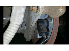
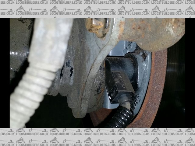
The sensor is a std in box honda s2000 3 wire ( so thinking Hall effect) gearbox sensor. The device is a 7 series acewell uni.t I was just going to
power it up at 12v, BUT, doubt has been cast on whether it would originally have been 5 volt, on the honda, and whether there would be any
relevance/problems to us powering it at 12volt now.
Thanks for the in depth reply but youv'e lost me at that level of discussion LOL.
If it looks wrong it probably is wrong.
|
|
|
02GF74
|
| posted on 2/1/16 at 11:04 AM |
|
|
Hmmmm i no nothing about that gearbox sensor. It could be optical but most likely hall or inductive.
If its been previously connected and working, can you put voltmeter on the sensor leads to see voltages, and rotate gearbox slightly to see voltage on
output.
Do you have wiring diagram to see it it was supplied with 12 or 5v.
|
|
|
omega 24 v6
|
| posted on 2/1/16 at 11:07 AM |
|
|
No wiring diagrams at the moment and its now in a MK2 escort so the original install is gone and I can't find one locally to measure the
voltage.
If it looks wrong it probably is wrong.
|
|
|
02GF74
|
| posted on 2/1/16 at 11:13 AM |
|
|
Googling seems to show it needs 5v.
This from maplin will sort that.
http://www.maplin.co.uk/p/ts78m05cz-05a-positive-fixed-voltage-regulator-to220-case-ql28f
7805 device, you can get it for less.
Then connrct output to speedo, if it doesnt work, it will need 5 to 12 v converter.
|
|
|
russbost
|
| posted on 2/1/16 at 11:20 AM |
|
|
Ok, this is quite a complex area, but will answer as best I can, I would emphasise I am NOT an electrical guru!
Most 3 wire hall sensors will work with the more modern Acewells, like 268/278. 5xxx, 6xxx, 7xxx MD052 & MD085 dashes, the older, cheaper dashes
have a slower processor that can't cope with the frequency of signals generated from a hall sensor
The green wire from the Acewell 7659 is floating at 5v, when it connects to earth via the reed switch supplied it senses this as the switch
continually opens & closes & that gives you the speed signal.
With most hall sensors you will have a 12v feed, an earth & the signal wire, most run the signal wire at 5v to 0, so as the hall sensor triggers,
if you have the signal wire connected to the Acewell green wire, the Acewell will sense this signal & run quite happily from this. A few (mainly
Ford I think) sensors run at 12v on the signal wire, this is too much for the Acewell which wants a max of 5v (needs around 2.5 - 2.7v to trigger), in
this instance, if you connect to one of these then it won't immediately damage the unit but it will switch on every block on the lcd display, so
it's pretty obvious there is something wrong, continued running like this will damage the dash. However if you insert a diode in the line such
that it can't pass the 12v to the Acewell then it will still register a speed signal as the hall sensor goes to ground. Just to add complication
not all hall sensors go to earth when in the off state, in which case the addition of a 1k resistor from signal wire to earth will allow the system to
work - like I said it can get a bit complex & we haven't even got into 2 wire sensors & abs sensors yet!
The simple answer to the Q is that in the vast majority of cases the Acewell will work fine from the hall sensor, a 5v sensor being best, if
you're having trouble still then give us a call or drop me an email
I no longer run Furore Products or Furore Cars Ltd, but would still highly recommend them for Acewell dashes, projector headlights, dominator
headlights, indicators, mirrors etc, best prices in the UK! Take a look at http://www.furoreproducts.co.uk/ or find more parts on Ebay, user names
furoreltd & furoreproducts, discounts available for LCB users.
Don't forget Stainless Steel Braided brake hoses, made to your exact requirements in any of around 16 colours.
http://shop.ebay.co.uk/furoreproducts/m.html?_dmd=1&_ipg=50&_sop=12&_rdc=1
|
NOTE:This user is registered as a LocostBuilders trader and may offer commercial services to other users
|
omega 24 v6
|
| posted on 2/1/16 at 11:37 AM |
|
|
many thanks to you all for answering. I think I have enough information to proceed now. I will go with a 5v feed and see where that takes me to.
Again Thank you very much everyone.
If it looks wrong it probably is wrong.
|
|
|
britishtrident
|
| posted on 2/1/16 at 01:01 PM |
|
|
quote:
Originally posted by omega 24 v6
many thanks to you all for answering. I think I have enough information to proceed now. I will go with a 5v feed and see where that takes me to.
Again Thank you very much everyone.
Yes a Hall Effect sensor is a switch if you need 5v on the output you need 5v on the input.
[I] What use our work, Bennet, if we cannot care for those we love? .
― From BBC TV/Amazon's Ripper Street.
[/I]
|
|
|
russbost
|
| posted on 2/1/16 at 02:13 PM |
|
|
quote:
Originally posted by britishtrident
quote:
Originally posted by omega 24 v6
many thanks to you all for answering. I think I have enough information to proceed now. I will go with a 5v feed and see where that takes me to.
Again Thank you very much everyone.
Yes a Hall Effect sensor is a switch if you need 5v on the output you need 5v on the input.
Not sure if there may be a slight misunderstanding here, the hall sensor (unless it's completely different to anything I've ever seen)
will have a 12v feed, & an earth - the 3rd wire will generate a frequency with a square wave, which will alternate between 0 & 5v, I'm
not quite sure what you mean by "go with a 5v feed"
I no longer run Furore Products or Furore Cars Ltd, but would still highly recommend them for Acewell dashes, projector headlights, dominator
headlights, indicators, mirrors etc, best prices in the UK! Take a look at http://www.furoreproducts.co.uk/ or find more parts on Ebay, user names
furoreltd & furoreproducts, discounts available for LCB users.
Don't forget Stainless Steel Braided brake hoses, made to your exact requirements in any of around 16 colours.
http://shop.ebay.co.uk/furoreproducts/m.html?_dmd=1&_ipg=50&_sop=12&_rdc=1
|
NOTE:This user is registered as a LocostBuilders trader and may offer commercial services to other users
|
omega 24 v6
|
| posted on 2/1/16 at 11:42 PM |
|
|
Well what I meant was id put a 12v to 5v dropper in line before the hall sensor.
My limited knowledge of these things made me ask the original question because I'd had some information that in its original form the sensor
would have had a 5v applied to it.
Then I wondered if it was safe/reasonable that it could/would work with a 12v supply to it. Then you guys came kindly answered with your thoughts and
I surmized that a 5volt supply was indeed the way to go.
So now I'm more confused than ever.
If it looks wrong it probably is wrong.
|
|
|
coyoteboy
|
| posted on 3/1/16 at 06:09 AM |
|
|
The problem is that there are literally dozens of types of hall sensor, switch, analogue output, all sorts of input voltage, all sorts of output
voltage (or current source, or active ground). The input to the speedo is also similarly complex. My best advice, in the absence of being able to test
it myself, is to get more info on the individual units.
|
|
|
russbost
|
| posted on 3/1/16 at 11:23 AM |
|
|
quote:
Originally posted by omega 24 v6
Well what I meant was id put a 12v to 5v dropper in line before the hall sensor.
My limited knowledge of these things made me ask the original question because I'd had some information that in its original form the sensor
would have had a 5v applied to it.
Then I wondered if it was safe/reasonable that it could/would work with a 12v supply to it. Then you guys came kindly answered with your thoughts and
I surmized that a 5volt supply was indeed the way to go.
So now I'm more confused than ever.
As coyoteboy has said there are loads of different types, by far the most common is as I've described with a 12v feed & 5v output, but as 5v
is quite common for ECU's & the like I can certainly conceive there may be units with a 5v feed. I would suggest either ask on the Honda
forums or get hold of a wiring diagram in which case if it's a 12v feed I would expect it to be fairly obvious.
I no longer run Furore Products or Furore Cars Ltd, but would still highly recommend them for Acewell dashes, projector headlights, dominator
headlights, indicators, mirrors etc, best prices in the UK! Take a look at http://www.furoreproducts.co.uk/ or find more parts on Ebay, user names
furoreltd & furoreproducts, discounts available for LCB users.
Don't forget Stainless Steel Braided brake hoses, made to your exact requirements in any of around 16 colours.
http://shop.ebay.co.uk/furoreproducts/m.html?_dmd=1&_ipg=50&_sop=12&_rdc=1
|
NOTE:This user is registered as a LocostBuilders trader and may offer commercial services to other users
|
obfripper
|
| posted on 3/1/16 at 10:56 PM |
|
|
From what i can see, the acewell dash is not designed to directly connect to a hall sensor of oe design.
The sensor will work with any 5-30vdc supply, it appears the acewell dash input is 5v max.
The input voltage is just to make the sensor switch, so long as it is a plain hall sensor with no active circuitry it will not feed this voltage to
the output, only connect the output to earth each time the trigger wheel passes the sensor.
The oe honda sensor will give a switching earth if wired; pin1: 12+ve pin2: output to dash green wire pin3: earth (pins numbered left-right with clip
of connector pointing upwards).
This may trigger the dash if there is enough pull up current from the dash when sensor is open resistance(mirroring the operation of the original
acewell reed switch).
If there is not enough current driving the pull up voltage, you will need to add a 1kohm pullup resistor between pins 1&2 and regulate the input
voltage to 5v to match the acewell max voltage, as the pull up resistor will bring up the output voltage to match the input voltage when the sensor is
open resistance.
There is one other issue with the honda gearbox sensor, it is either 46 or 48 pulses per prop revolution, equating to about 190,000 pulses per mile
with escort running gear.
Going by the spec of the acewell 7659, it will read up til about 120mph and then run out of sensor bandwidth.
If your dash is a lower spec model than this, it may not be capable of even close to this.
The original s2000 clocks have a /40 divisor to generate the signal for the rest of the honda control units, as the honda body/chassis ecu standard is
4000 pulses per mile.
If you can't use the signal from the s2000 sensor, you can wire up a hall sensor in the same way and fit it to the rear axle pointing at the
rear of the wheel studs on the hub.
This will give you a simpler 4 pulses per wheel revolution, or ~4000 pulse per mile.
I have an older honda speedo head in my car with a vauxhall hall crank sensor driving it in this way.
Hall sensor english axle
Dave
|
|
|
russbost
|
| posted on 4/1/16 at 10:41 AM |
|
|
I wasn't personally involved with the design of the Acewell speedo, however I've just spoken to the man that was! I can assure you ALL of
the modern Acewell dashes, & in fact this now includes everything but the 258, 260, 1600 & 3100, were most certainly designed to work with a
Hall sensor, Acewell sell their own 3 wire sensor, the Ace S9 which is a 3 wire sensor & will work with all the new dashes.
It is correct the dashes are designed for a max 5v input on the speed sensor wire as I'd already stated in previous post
I had already also mentioned the 1k pull up resistor if the sensor doesn't go to earth, which some don't
I've also done some more research on the Honda S2000 sensor & it is somewhat unusual, it DOES have just a 5v supply voltage, if using the
original ECU this isn't a problem otherwise you'd need the LM7805 voltage reg as already discussed above. However, it also has just 1.2v
square wave output, so insufficient to drive the Acewell without additional parts - see copy of email further down
The calcs given by obfripper above are some way out (sorry!), even assuming a tyre circumference of 1600mm (which is very low) & a diff ratio of
3.5 you would get a max speed readout of 153mph, if diff is lower or tyres larger then that can only go up
You could use the Acewell S9 Hall sensor in the manner described above, but tbh if going that route you might just as well save the money & use
the magnet & reed switch supplied, in which case you have a max speed readout of 248.5mph, I doubt you'll be going quicker than that!
Having contacted Acewell I've been able to get a copy of an email from someone who has actually made a similar installation back in 2011, see
below, I'm sure one of the solutions here (either above or below) will be of help
Hello
> > I have a Honda S2000 gearbox and wish to use its speed sensor which
> > generates 5V pulses proportional to the vehicle speed, would I be able to
> > use this as an input to the ACE-7659? If not, what must I convert the sensor
> > output into for it to work? (I want to avoid having a separate speed
> > sensor).
> > My engine has a coil pack on top of each spark plug, therefore no HV leads,
> > so I was wondering if I can use a 12V pulse from my Emerald ECU to give the
> > tacho input? If not, then what form must the signal be for it to work with
> > this unit?
> > Thank you for your time
> >
Hi,
> > Yes it will work with the 5v pulses as long as you have a pull down resistor
> > for the off state as the input to the acewell floats at 5v. A 1m ohm
> > resistor works fine. You can use the one in the kit if you don't need it for
> > the rpm
> > Tach may work the way you want. If it doesn't then solder onto one of the
> > trigger cables going to one of the active caps
> > Best Regards
Thanks for your reply.
> >
> > I've bought the ACE-7659 and all has worked except the speedo. Although the
> > sensor works on 5V I found output pulse amplityude was only a fraction of
> > that.
> >
> > The output from my gearbox only gave 1.2V and the ACE 7659 didn't read any
> > speed when I was moving. What I've done is used an op-amp to increase the
> > size of the pulse to generate a 3V amplitude or a 6V amplitude. Can I feed
> > the output directly into the ACE 7659? (I'm afraid if the ACE 7659 speed
> > input floats at 5V then a higher voltage could damage your system, is this
> > the case?).
> >
> > If I need to bring the voltage down then I'll either put a couple of diodes
> > in series to knock off a few volts or I'll put a resistor in series with the
> > input to limit any potential current draw into your system, ... if needed.
> > What do you think?
Can you send over a circuit diagram of what you've come up with and
> I'll check for you.
> Basically, the green wire on the acewell floats at 5v and works by
> pulling the voltage on the wire down by using a resistor or simulated
> resistor. If you put a 3v signal into it then it'll still float at 5v.
> If you've got your op-amp designed in such a way that it switches
> between 3v and 0v - a real 0v with a low resistance between the wires
> rather than floating then it'll work.
> There should be no issues putting your 6v op-amp onto the wires, but
> try your 3v setup first.
> If you have no success then you could could go as simple as putting an
> NPN transistor driven from your sensor between the green wire and -ve
> and switch it from your sensor, thus pulling the green wire to ground,
> or allowing it to float at 5v. I'm not sure what size biasing resistor
> you'd need on the base though.
>
> Please let me know how you get on
I no longer run Furore Products or Furore Cars Ltd, but would still highly recommend them for Acewell dashes, projector headlights, dominator
headlights, indicators, mirrors etc, best prices in the UK! Take a look at http://www.furoreproducts.co.uk/ or find more parts on Ebay, user names
furoreltd & furoreproducts, discounts available for LCB users.
Don't forget Stainless Steel Braided brake hoses, made to your exact requirements in any of around 16 colours.
http://shop.ebay.co.uk/furoreproducts/m.html?_dmd=1&_ipg=50&_sop=12&_rdc=1
|
NOTE:This user is registered as a LocostBuilders trader and may offer commercial services to other users
|
02GF74
|
| posted on 4/1/16 at 01:22 PM |
|
|
quote:
Originally posted by russbost
I've also done some more research on the Honda S2000 sensor & it is somewhat unusual, it DOES have just a 5v supply voltage, if using the
original ECU this isn't a problem otherwise you'd need the LM7805 voltage reg as already discussed above. However, it also has just 1.2v
square wave output, so insufficient to drive the Acewell without additional parts - see copy of email further down
Russ - do y9ou know if the signal 0 V to 1.2 V square wave or 1.2 V amplitude?
quote:
Originally posted by russbost
> Basically, the green wire on the acewell floats at 5v and works by
> pulling the voltage on the wire down by using a resistor or simulated
> resistor.> Please let me know how you get on
Ok, then that needs open collector circuit to drive it as speculated above. Simplest would be single transistor in common emitter mode,
example below - it will invert the signal but that shouldn't matter.

|
|
|
russbost
|
| posted on 4/1/16 at 01:53 PM |
|
|
Sorry, I don't really have any further info than what I have already posted, as stated I am no electrical guru, just have a large collection of
data on fitting Acewells, hence why I posted the whole email from them rather than picking bits out as I might have missed something essential. When I
spoke to Acewell they confirmed that the system as described in the email did work for the guy, so I would guess that the output is a genuine 0v to
1.2v square wave, however if not, once amplified the signal would still work (I believe) if you pull the wire to ground thro' the 1k
resistor.
They did mention using the single transistor as amplifier, but I'm sorry I get lost once we get into NpN & PnP, collectors, bases &
such, my (limited) electrical knowledge dates from school & polytechnic some nearly 40 years ago - it's slightly rusty! 
I no longer run Furore Products or Furore Cars Ltd, but would still highly recommend them for Acewell dashes, projector headlights, dominator
headlights, indicators, mirrors etc, best prices in the UK! Take a look at http://www.furoreproducts.co.uk/ or find more parts on Ebay, user names
furoreltd & furoreproducts, discounts available for LCB users.
Don't forget Stainless Steel Braided brake hoses, made to your exact requirements in any of around 16 colours.
http://shop.ebay.co.uk/furoreproducts/m.html?_dmd=1&_ipg=50&_sop=12&_rdc=1
|
NOTE:This user is registered as a LocostBuilders trader and may offer commercial services to other users
|
obfripper
|
| posted on 4/1/16 at 09:51 PM |
|
|
i'm pretty sure when i have scoped a good s2000 vss it was 5v square wave on the output, i didn't save the original trace, but i have
attached the screens from the guided fault finding on my oscilliscope for an s2000 that show the same.
Plug details
Waveform details
I was meaning that it was not designed for an OE hall sensor in that the 7659 model does not give a +12v or +5v output to power a sensor that
may require it, you have to piggyback an existing +12v or +5v system or make your own supply, i'm assuming the better models may have a 3 pin
plug with all this ready to go.
By what is described in the email from acewell, the supplied voltage at the green signal wire did not have sufficient current (5-10mA) to pull it up
to 5v when the sensor is open, which would make sense as you want the absolute miniumum current(in the nA range) flowing through a reed switch so the
contacts have maximium working life.
A pullup resistor is all that is required to fix this, i suspect acewell's own sensor has an integrated resistor.
You need something like this: (thanks to MSEXTRA.COM)

The other thing that may have occured for this low voltage signal is a failure of the vss hall sensor, as the sensor goes to earth when is supposed to
be open, it will still produce a small signal, i have changed 1 from 3 customer cars for a no signal fault like this.
Regarding the max speed displayable, a 3.54 diff with a .81 top gear and a 9k rev limit is going to gear you for 203mph on 185 60 13 tyres, a more
useable 4.8 diff will allow a top speed of 150mph but will stop reading at 120mph when it gets past 7000 pulses per second / 7300rpm in top
gear.(Edit: a bit of oops, i forgot about the primary reduction gear changing effective diff ratios with 3.54 becoming 4.1 with 175mph top speed, and
4.8 becoming 5.5 with a 129mph top speed, reducing resolvable top speed to 105mph)
This is the fault of honda using such high resolution triggers on the s2000, i have not encountered any other oe sensors that have such a high pulse
rate, the only speedos that have the required bandwidth are the vdo ones(max 399,999 pulses per mile), the more common caerbont/smiths/rmd cut off at
125,000 pulses per mile which is similar to the acewell.
The only way to display the full speed range using your dash and gearbox sensor is to use a d type flip flop frequency divider like this:

This would halve the frequency of the gearbox output, and give you a more managable signal, you can daisychain these together to provide a further
frequency reduction.
I'm sure a circuit would be simple enough to draw up, there are loads of different ic's that you can choose from, the surface mount stuff
probably isn't useable unless you know someone who can prototype a small board.
Hopefully there is enough info here to guide you to a solution!
Dave
[Edited on 4/1/16 by obfripper]
|
|
|
02GF74
|
| posted on 6/1/16 at 12:20 PM |
|
|
There are 4 parts to getting this working. I've contacted Acewell and update as below.
1. power for sensor - internet search indicates S2000 needs 5 V; this is sorted using 7805 or LM317.
2. sensor signal - conflicting information. The only sure way is to measure the sensor.
3. Acewell input. This is pulled up to 5 V via a high value resistance and needs a rising or falling edge past 2.5 V. It must not exceed 5 V.
4. sensor frequency. Need to know number of pulses per mile. It may require a divider circuit.
|
|
|
russbost
|
| posted on 6/1/16 at 12:30 PM |
|
|
quote:
Originally posted by 02GF74
There are 4 parts to getting this working. I've contacted Acewell and update as below.
1. power for sensor - internet search indicates S2000 needs 5 V; this is sorted using 7805 or LM317.
2. sensor signal - conflicting information. The only sure way is to measure the sensor.
3. Acewell input. This is pulled up to 5 V via a high value resistance and needs a rising or falling edge past 2.5 V. It must not exceed 5 V.
4. sensor frequency. Need to know number of pulses per mile. It may require a divider circuit.
Unless the sensor has a ridiculous no. of pulses (over 50) or you're running a crazy low diff (like 4.1 or something) or tyres smaller than
1600mm circumference you won't need the divider circuit
I no longer run Furore Products or Furore Cars Ltd, but would still highly recommend them for Acewell dashes, projector headlights, dominator
headlights, indicators, mirrors etc, best prices in the UK! Take a look at http://www.furoreproducts.co.uk/ or find more parts on Ebay, user names
furoreltd & furoreproducts, discounts available for LCB users.
Don't forget Stainless Steel Braided brake hoses, made to your exact requirements in any of around 16 colours.
http://shop.ebay.co.uk/furoreproducts/m.html?_dmd=1&_ipg=50&_sop=12&_rdc=1
|
NOTE:This user is registered as a LocostBuilders trader and may offer commercial services to other users
|
obfripper
|
| posted on 8/1/16 at 12:35 AM |
|
|
I've had a hunt round, and found a copy of the s2000 service manual.
Page 1
Page 2
Step 7 is for checking the pullup voltage from the clocks, it is looking for 5v with the sensor plug disconnected.
This is what needs to be recreated to get a signal you can use, and diagnose any faults in the future using the original diagnostic steps.
I've roughed up a couple schematics that should give this functionality, one with a divider circuit, and boxed in the components that would make
up the driver board.
The LM7805 will require heatsinking, all the other components should produce no significant heat.
Vss driver circuit
Vss driver with divider circuit
If anyone can spot any errors/improvements, point them out & i'll correct them.
Are you using the s2000 engine and original ecu with this gearbox?
If you are, a more complex divider circuit is necessary, as in the s2000 there are 160,000 pulses per mile sent to the clocks, the clocks divide this
by 40 and output this 4000 pulse per mile signal back to the engine ecu.
The ecu uses this to work out which gear you are using and apply the correct map for that gear, your wheel size / diff will not affect this.
Without this signal the engine will be stuck in limp mode with restricted rpm and power.
To replicate this signal, a cd4059 programmable divder would be needed to replace the CD4013 on the divider circuit to get a factor of 40 divisor, a
good read of the datasheet would be in order as it requires a more complicated circuit.
Dave
|
|
|
gremlin1234
|
| posted on 8/1/16 at 01:13 AM |
|
|
quote:
The LM7805 will require heatsinking, all the other components should produce no significant heat.
with the power requirements of this
circuit, I don't think any heat sync will be required.
also someone suggested the
http://www.maplin.co.uk/p/ts78m05cz-05a-positive-fixed-voltage-regulator-to220-case-ql28f
which does not require external components, (apart from the pull up resistor !!!)
|
|
|
obfripper
|
| posted on 8/1/16 at 08:01 AM |
|
|
The diodes and capacitors are to protect the circuit against voltage spikes and smooth any jitter in the voltages.
They aren't absolutely necessary, but will make the circuit more durable.
The 7805 will produce some (~3w) heat with no load due to the way it works, a buck converter would be more efficient but would require a more
complicated circuit.
Dave
|
|
|