Jamesc
|
| posted on 12/1/16 at 08:58 AM |

|
|
Hall Effect Sensor
Hi All,
I use the Hall Sensor that was supplied with the ETB DD2 to supply a speed signal to the dash.. But, I also need a speed signal to supply a gear
indicator.
I have read on here that it's not recommended to use the same sensor signal for two things - Is that correct?
If so, I was planning on wiring up a second sensor to supply the pulse signal to the indicator, but I'm not sure what type of hall sensor I
require? Is there a kit or something? I believe I require a 5v signal, so may have to step the voltage down.
By the way, engine is zx12 and the speed sensor is not present.
Thanks in advance,
James
|
|
|
|
|
theprisioner
|
| posted on 12/1/16 at 09:21 AM |
|
|
The reason you don't supply more than one device from the same sensor is the output from most of these devices is "open collector"
and essentially a current driven output. If you connect several devices to this it will attenuate the signal in an unpredictable way. If however you
buffer the signal in a small device (mounted in a box) you can drive as many signal receiving devices as you like. I only mention this as hall speed
detectors can be expensive.
Something like this perhaps? (You would have to try it)
http://pdf.datasheetcatalog.com/datasheet/texasinstruments/buf04701.pdf
http://sylvabuild.blogspot.com/
http://austin7special.blogspot.co.uk/
|
|
|
Jamesc
|
| posted on 12/1/16 at 10:49 AM |
|
|
Ah OK, that makes sense, thanks for the explanation.
I'm not overly clued up on electronics, so it may be easier for me to install a second stand alone sensor to feed the gear indicator. I
don't want to end up with an unreliable signal to the dash! Unless the buffer amplifier is a lot more simple than I imagine?
What type of hall sensor would be needed for a pulse? Do they require drivers or controllers?
If anyone could point me in the direction of some information online, that would be great. I can't seem to find anything of relevance, most
likely because I'm not sure what I'm looking for!
|
|
|
theprisioner
|
| posted on 12/1/16 at 05:23 PM |
|
|
Most of the sensitive (quality) senders are quite expensive:
http://www.demon-tweeks.co.uk/motorsport/gauge-sender-units/revotec-electronic-speedometer-sensor
But they can detect on e.g. the bolts retaining your front disk.
That is why I was suggesting a buffer for multiple receiving systems. There are cheaper sensors but watch the sensitivity required to trigger them
some need magnets attached to the thing rotating.
http://sylvabuild.blogspot.com/
http://austin7special.blogspot.co.uk/
|
|
|
Jamesc
|
| posted on 12/1/16 at 07:42 PM |
|
|
More expensive than I thought... The ETB ones are £30 and are supplied with magnets, thought I may be able to buy one for a tenner!
Is the buffer amplifier something I could buy as a unit? i.e. simply joining wires? When searching, all I seem to get is the IC, which isn't out
of the question, but it'll take me a while to understand it...
Thanks for your help mate, it's all new to me.
|
|
|
gremlin1234
|
| posted on 12/1/16 at 10:39 PM |
|
|
the ones that induce and then detect a magnetic field are more expensive, but are now really common. (think abs detectors; cheap ones circa £15 .)
with a separate magnet they cost less.
for detector only, many computer fans have one built in, as do many push bike speedo's.
these would be fine for showing speed measurement etc. but as soon as you go for detecting crank position/ abs/ anything that is a safety concern,
just go for the manufacturers recommended part. (or direct replacement)
|
|
|
theprisioner
|
| posted on 12/1/16 at 11:17 PM |
|
|
I have not seen one as a unit, Maplin have all the bits if you want to "have a go".
http://sylvabuild.blogspot.com/
http://austin7special.blogspot.co.uk/
|
|
|
02GF74
|
| posted on 12/1/16 at 11:21 PM |
|
|
Depends on input stage to the speedo.
It may be looking for a voltage level or need open collector driver, the latter effectively connects the input stage to ground.
Connecting to both inputs may be ok but a buffer for sure would ensure there is no damage.
Simplest would be non inverting ttl or cmos device, the latter can be supplied on 12 v, these are available with open collector stages.
|
|
|
Neville Jones
|
| posted on 13/1/16 at 11:14 AM |
|
|
If you put the signal into an opamp, wired as a buffer/voltage follower then feed your gear indicator with the output, you'll not have a
problem. I've done exactly this on previous builds for gears and speed and gear readout. Also used abs sensors on each corner then fed into the
opamps and Arduino for powwer interrupt for traction control sort of thing.
The buffer from TI mentioned above has the internal wiring already there, so you just need an input resistor and maybe one on the output to get what
you want.
Get some bits from Maplins, predrilled board and wire, and give it a go yourself. Not rocket science by a long way.
Plenty of circuits online, images and words, for what is a very simple bit of work.
Cheers,
Nev,
|
|
|
Jamesc
|
| posted on 13/1/16 at 01:00 PM |
|
|
Thanks for all the replies, I'm definitely feeling more informed.
Would something like this work?
[url=http://www.ti.com/lit/ds/symlink/opa377.pdf[/url]
Looking at the the OPA377 - Is it as simple as:
Pin 5 - 5v supply (from a buck converter)
Pin 4 - Not connected
Pin 3 - 5v signal from sensor
Pin 2 - Ground
Pin 1 - Signal to two devices
Or find something similar that will accept a 15v input supply which removes the need for the converter?
There was a lack of info on the Maplin site and I couldn't work out which component I needed. The above one can be sourced from RS though. I
also couldn't find anywhere that sold the TI component that was linked to above...
I understand that this is by no means a complex circuit, but as my electrical knowledge is next to zero (especially with ICs etc.), it seems complex
to me!
|
|
|
theprisioner
|
| posted on 13/1/16 at 10:23 PM |
|
|
Wide band amplifiers in cars is not the answer (IMO) something like this might be:
https://www.fairchildsemi.com/datasheets/MM/MM74C906.pdf
If I knew more about the input specs of the receiving devices that would help?
http://sylvabuild.blogspot.com/
http://austin7special.blogspot.co.uk/
|
|
|
Jamesc
|
| posted on 14/1/16 at 08:57 AM |
|
|
The input specs of the two devices is the main problem - I can't find what they are..
One is an ETB DD2. I measured the sensor plug (without the sensor plugged in), it has 3 pins - 2 are 5v and 1 is ground.
The other is a Digitool Gear Indicator. The instructions say to connect the speed input to either the speedo signal wire or directly to the the speedo
sensor.
http://www.datatool.co.uk/PDF/DIGI-Installation-i
nstructions-Electronic-speedometer-version.pdf
Would the gear indicator have any sort of compensation seeing as it says it can connected directly to the speed sensor?
|
|
|
Neville Jones
|
| posted on 14/1/16 at 10:32 AM |
|
|
I've been using the LM2902 from RS with no problems. Part #806-2784 or 661-0518 .
Cheers,
Nev.
|
|
|
theprisioner
|
| posted on 14/1/16 at 11:03 AM |
|
|
I have had a look at the manual and as you say there is very little information. However it is safe to assume the signal are 5V compliant. The reason
I say this is the internal logic computers etc will have a 5V regulator to isolate it from all the crap on the car +12V. That means that any buffer
will have to be fed via 5V to be compatible open collector or otherwise. So you need a circuit diagram to start with, sketch out what you need in the
form of a block diagram first and we will take it from there. However you are starting don the road of purchasing a list from Maplin and soldering it
together and trying it out yourself? Are you up for that?
http://sylvabuild.blogspot.com/
http://austin7special.blogspot.co.uk/
|
|
|
Jamesc
|
| posted on 14/1/16 at 11:36 AM |
|
|
Well initially I wasn't keen, I'll openly admit it's beyond my skills level.
However, with a little help I'm sure it's achievable. I'm comfortable with assembly/testing, it's the actual knowledge of what
does what and what goes where that's missing.
I'll sort a block diagram shortly of what I want to achieve, won't be so useful on the circuit diagram though. I assume this will be less
expensive than a separate hall sensor?
|
|
|
Jamesc
|
| posted on 22/1/16 at 04:26 PM |
|
|
Just to close this thread off nicely...
Alistair (theprisoner) helped me design a circuit that would take the Hall effect sensor signal and effectively amplify it in to two signals. I have
now built this circuit, fully tested it and can confirm that it works a treat with both the DD2 and the Digitool Gear Indicator. I have written a
summary of what we built and the specific components we used below.
The final circuit diagram is as follows:
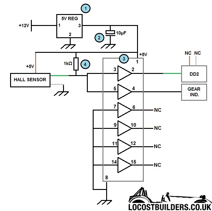
The colours coming from the DD2 match up with the colours on the hall sensor in the original circuit. These are the colours that the wires in my DD2
were (Note: Grey is actually white). The brown and grey wires from the DD2 are left NC (Not connected).
For an electronics novice like me, I thought it best to number the components (Blue circles) and list what they are:
1 - 5V Regulator (Maplin Code: N67CA)
2 - 10µF 16V Capacitor (Maplin Code: AT98G)
3 - 4050 CMOS Logic HCF/HEF (Maplin Code: QX22Y)
4- 1k Ohm resistor (Maplin Code: M1K)
Newbie Notes:
- 5V reg has three 'legs': 1 - +12V, 2 - Ground (Chassis), 3 - +5V (They are numbered from Left to Right looking at the front - Diagrams
online)
- Ensure capacitor is installed correctly, one leg is +
- The IC has a small 'U' shape notched out of it which shows the top. Diagrams are readily available online for the pin numbers.
- Resistor can be fitted either way
I also purchased the following items to complete the project ready for installation:
Veroboard - FL17T
Project Box - N23HG
IC Socket - FZ49D
Terminals (3way and 2way) - RH81C
Hope that helps someone, someday! I will post a picture of my finished circuit later. Thanks once again to Alistair for all of his help and patience
with me and my limited knowledge!
James
|
|
|