mark chandler
|
| posted on 10/5/16 at 02:26 PM |

|
|
Tachometer issues.... I cannot make it work :(
I purchased one these
12000RPM LCD Digital Odometer Speedometer Tachometer F1 2 4 Cylinders Motorcycle
And very nice it looks as well but connecting the tachometer pickup as follows:
Connect to the CDI output... Zilch
Connect to the coil packs .... Zilch
Connect to the injectors ..... Zilch
Wrap the feed wire around an HT lead a dozen times, it shows the idle speed  but Rev the engine and it creeps up to around 2000rpm but does not go
above this, I have tried less turns, around 4 and it does not sense anything. but Rev the engine and it creeps up to around 2000rpm but does not go
above this, I have tried less turns, around 4 and it does not sense anything.
Connect to the inductive pickup for the CDI unit and it shows 6000rmp at idle and responds immediately if you Rev the engine.
I have tried adding a 10k resistor in line and included a Zener diode when looking at the usual sources .... Zilch everything is the same as above.
Emailing China has not helped, however I did get them to send me a second one on the basis that mine is faulty but they both behave in the same way so
I now have a pair.
Anyone got any ideas on how to get these to work?
There is a menu, only allows you to switch between 2 & 4 cylinders, set tyre diameter and fuel sensor sensitivity.
|
|
|
|
|
coozer
|
| posted on 10/5/16 at 02:35 PM |
|
|
I bought a big tablet from China and its now a shiny table top....
This made me chuckle
Note:
The pointer offset does not affect the measurement accuracy, you can put the pointer to the in place. Please buy cautiously.
1972 V8 Jago
1980 Z750
|
|
|
mark chandler
|
| posted on 10/5/16 at 02:50 PM |
|
|
I do not know what that bit means, I was expecting it to have a manual red line pointer but it is just a sealed unit so nothing to twiddle externally
as such.
I,m sure if I can get the right feed to it then away it will go, dumped the bike clocks as I wanted the adjustable speedo...

It looks like I have swapped a working tachometer for a working speedo.
With wire wrapped around an HT lead has anyone got any ideas of the voltage that is being pushed into the tachometer, is it just that 12v on the CDI
unit is not enough?
Although I expect the voltage on the inductive pickup must be pretty low...
[Edited on 10/5/16 by mark chandler]
|
|
|
britishtrident
|
| posted on 10/5/16 at 03:18 PM |
|
|
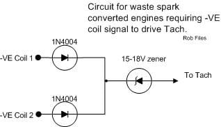
What is the coil arangmement is it wasted spark ie. one double ended coil supplies two cylinders? If so try wrapping the wire round athe plug lead on
the opposite side of the coil.
With wasted spark one lead gets a positive spark the other a negative.
[I] What use our work, Bennet, if we cannot care for those we love? .
― From BBC TV/Amazon's Ripper Street.
[/I]
|
|
|
mark chandler
|
| posted on 10/5/16 at 03:19 PM |
|
|
That's interesting, I did not know that just assumed that both coils would cause a spark positive to negative.
It's wasted spark so I will try the in a minute
Also how many turns, is there an optimum number?
[Edited on 10/5/16 by mark chandler]
|
|
|
gremlin1234
|
| posted on 10/5/16 at 03:31 PM |
|
|
this advert for one
http://www.banggood.com/12000-RMP-LCD-Digital-Speedometer-Odometer-Motorcycle-1-4-Cylinders-p-972677.html
has quite a lot of info.
especially looking at the questions/answers
|
|
|
mark chandler
|
| posted on 10/5/16 at 04:19 PM |
|
|
It looks like someone else has the same problem then with RPM and it will not work off the coil pack wires, I think the CDI until switches to earth
which could be the problem on the coil packs which is the same as the injectors.
|
|
|
Ben_Copeland
|
| posted on 10/5/16 at 04:41 PM |
|
|
My rev counter used to come off the wasted spark. You connect it to both signals with a diode between to stop them shorting out.
Mine comes from ecu now but it worked ok from coils
[Edited on 10/5/16 by Ben_Copeland]
Ben
Locost Map on Google Maps
Z20LET Astra Turbo, into a Haynes
Roadster
Enter Your Details Here
http://www.facebook.com/EquinoxProducts for all your bodywork needs!
|
|
|
Ben_Copeland
|
| posted on 10/5/16 at 04:50 PM |
|
|
Ben
Locost Map on Google Maps
Z20LET Astra Turbo, into a Haynes
Roadster
Enter Your Details Here
http://www.facebook.com/EquinoxProducts for all your bodywork needs!
|
|
|
mark chandler
|
| posted on 10/5/16 at 05:42 PM |
|
|
I,ve done the Zener diode, albeit off just one coil pack... Nada
I have now wrapped the wire around the second coil pack lead, flat line on this one as well ...
It's clear that a nice 12v signal (which should be perfect for most tachometers is not going to work on these ones, very annoying.
weird that it can work off the CDI input, I will tap into the alternator yellow wires tomorrow and see if that gets me an approximation of RPM.
[Edited on 10/5/16 by mark chandler]
|
|
|
britishtrident
|
| posted on 10/5/16 at 06:55 PM |
|
|
Normally on all 2 wire coils the tacho is triggered on the negative side of the coil, the positive side should be near constant battery voltage no
signal for the tacho to work off.
[Edited on 10/5/16 by britishtrident]
[I] What use our work, Bennet, if we cannot care for those we love? .
― From BBC TV/Amazon's Ripper Street.
[/I]
|
|
|
mark chandler
|
| posted on 10/5/16 at 07:42 PM |
|
|
I have tried both sides, still no good
|
|
|
twybrow
|
| posted on 10/5/16 at 07:46 PM |
|
|
Try a 1 M.ohm resistor. I had the same issue with my Koso, and no amount of changing the source or use of a dropdown resistor worked. Adding a 1 M.ohm
resistor has stabilised it, so no more bouncing tachometer (connected on the signal wire from the coil on plug).
|
|
|
mark chandler
|
| posted on 10/5/16 at 09:10 PM |
|
|
1M. 
I have wondered about dropping the voltage down incase this is the problem, it's not a jumping tachometer, nothing at all on the main sources.
|
|
|
gremlin1234
|
| posted on 11/5/16 at 11:36 AM |
|
|
quote:
Originally posted by twybrow
Try a 1 M.ohm resistor. I had the same issue with my Koso, and no amount of changing the source or use of a dropdown resistor worked. Adding a 1 M.ohm
resistor has stabilised it, so no more bouncing tachometer (connected on the signal wire from the coil on plug).
would that be a 1M pull up
resistor?
|
|
|
twybrow
|
| posted on 11/5/16 at 12:17 PM |
|
|
quote:
Originally posted by gremlin1234
quote:
Originally posted by twybrow
Try a 1 M.ohm resistor. I had the same issue with my Koso, and no amount of changing the source or use of a dropdown resistor worked. Adding a 1 M.ohm
resistor has stabilised it, so no more bouncing tachometer (connected on the signal wire from the coil on plug).
would that be a 1M pull up
resistor?
No, inline with the signal. I backed it up with a 10k.ohm pull down, but the inline made all the difference.
|
|
|
gremlin1234
|
| posted on 11/5/16 at 07:02 PM |
|
|
quote:
No, inline with the signal. I backed it up with a 10k.ohm pull down, but the inline made all the difference.
ok, I can see how that
would work too ;-)
|
|
|
mark chandler
|
| posted on 11/5/16 at 08:15 PM |
|
|
So you took tachometer lead to earth via a 10k resistor and collected the signal from the coil pack with a 1m resistor?
So have effectively dropped the input from 13.4v down to 0.134v
|
|
|
gremlin1234
|
| posted on 11/5/16 at 09:18 PM |
|
|
quote:
So have effectively dropped the input from 13.4v down to 0.134v
yep, but the 'zero volt' signal is much better defined.
certainly worth trying.
or try with both resisters at say 100K
|
|
|
Oddified
|
| posted on 12/5/16 at 05:33 PM |
|
|
You really need to know what signal the tacho is designed for, 5v or 12 v pulses, pull up or pull down etc. Once you know that making it work would be
relatively simple otherwise it's stabs in the dark.
Ian
|
|
|
mark chandler
|
| posted on 12/5/16 at 07:15 PM |
|
|
Unfortunately there is very little info on these, you only know how to wire it by googling as they come with zero instructions
Lots of sellers on eBay, some include the wiring instructions with the advert, it's a real shame as they do look ideal.
|
|
|
Oddified
|
| posted on 12/5/16 at 08:28 PM |
|
|
Had a quick look, and the key part of interest is;-
Engine rotate speed comes from the ignition signal. The sensor wire is normally contacted with the positive side of the magnetor or directly wired on
the rectifier.
I suspect you'll need a +/- signal and you'll need to do a bit of jiggery pokery with a resistor/capacitor to get your rpm pulse to swing
both + and -.
Ian
|
|
|
mark chandler
|
| posted on 13/5/16 at 06:22 AM |
|
|
Thanks Ian, that does confirm why it works off the CDI input.
Have you any idea what I need to make the CDI square wave output pulsed DC into an A/C signal.
Googling is not helping me to get from pulsed DC to AC with something very simply, my grasp of electronics is limited
[Edited on 13/5/16 by mark chandler]
|
|
|
Oddified
|
| posted on 13/5/16 at 08:06 AM |
|
|
Assuming there is some input resistance to gnd on the tacho input, connect a cap in series in the wire from the tacho to where ever you know you have
a nice rpm signal. Without knowing the input resistance of the tacho i'd try 0.1uF, 1uF and 10uF (if using electrolytics, neg leg to the tacho).
That should do it, if not you might also need to add a resistor between the gnd and tacho input (a cap/resistor combo that normally works is 10uf and
1k5 resistor).
Ian
|
|
|
mark chandler
|
| posted on 13/5/16 at 12:12 PM |
|
|
Thanks Ian, I will try a later on and report back.
|
|
|