John Bonnett
|
| posted on 13/10/22 at 12:05 PM |

|
|
An alternator question for Auto electricians
I'm using an alternator from a MK4 1.25 Fiesta (2002) which has a main stud for the power output and a two contact supplementary terminals, one
of which I believe goes to the ECU which I am not using and the second which I believe is for the ignition warning light.
I would have expected one of the contacts, the one to the ignition warning light would go to earth through the alternator casing but apparently, it
doesn't. Multimeter set to Ohms one contact on the wire and the other on the casing.
I would appreciate any help please.
Thank you.


|
|
|
|
|
Mr Whippy
|
| posted on 13/10/22 at 12:59 PM |
|
|
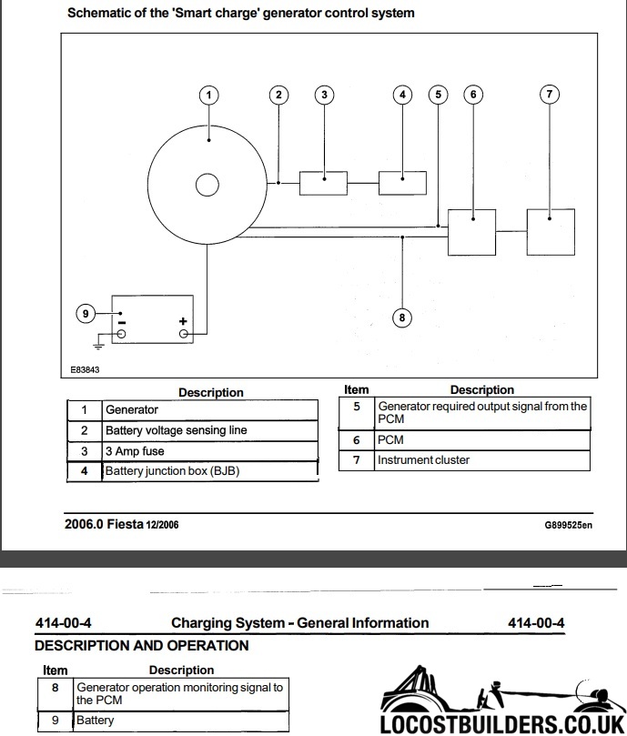
You have the same engine and alt as in my Fiesta. Maybe this might help but below is the only info I can find on the operation of the Alt in Fords
workshop manual. Most I don't really follow but might be helpful. Seems an overcomplicated way it operates. Sadly I can't find any info on
wire colours or connections.

|
|
|
adithorp
|
| posted on 13/10/22 at 01:11 PM |
|
|
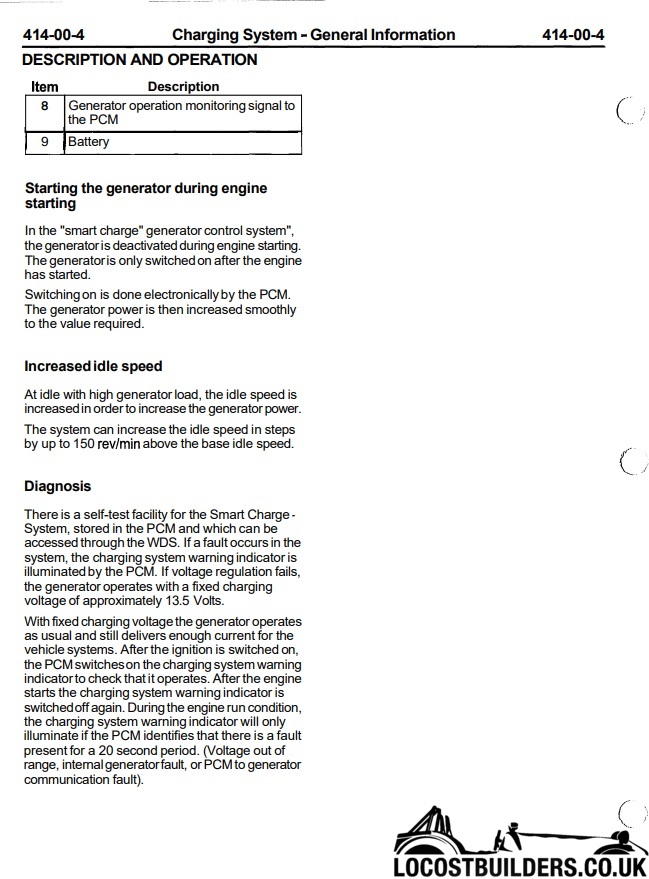
The Fiesta has smart charge system rather than old school analog one. Not dure there's an easy work-around (not my field). Could be you need a
different alt'.
"A witty saying proves nothing" Voltaire
http://jpsc.org.uk/forum/
|
|
|
John Bonnett
|
| posted on 13/10/22 at 01:15 PM |
|
|
Mr Whippy thank you.
I am hoping that the alternator will work without the smart charge input from the ecu. The thing I want to ascertain is which wire is the one that
goes to the ignition warning light and as I understand it when ignition is On, but without the engine running, power from the ignition switch lights
the ignition warning lamp and earths through the alternator. This is the exciter. When running, the alternator send 12 volts in the opposite direction
and the ignition lamp goes out. That's why I expected one of the wires to go to earth but seemingly not so.
|
|
|
Mr Whippy
|
| posted on 13/10/22 at 02:37 PM |
|
|
I think in this case after reading the text, there is no wire going directly from the alternator to the ignition light. Instead there is a signal from
the alternator sent to a processer that is in turn controlling the light, depending on if it is happy with what signals it see's from the
alternator. It also seems that the processor can turn on an off the alternator, maybe this is a simple 12 voltage as normal but doesn't answer
how you are meant to get the light to function if not using the original processor. I have damaged my cars alternator in some way and the light
refuses to go out, yet the charging voltage is exactly correct so it definitely doesn't work like an old car.
For such a simple car, the Fiesta electrics seems is a hellishly complicated!
|
|
|
adithorp
|
| posted on 13/10/22 at 02:37 PM |
|
|
Don't think these work that way... where's OBfripper when you need him?
"A witty saying proves nothing" Voltaire
http://jpsc.org.uk/forum/
|
|
|
John Bonnett
|
| posted on 13/10/22 at 03:09 PM |
|
|
Thank you for your replies but all is well now. For some reason that I don't understand, using the multimeter set to ohms, there is no route to
earth when connecting the body of the alternator to either of the two pins. However, by connecting a lamp to battery positive and sending the earth
connection from the lamp to the alternator terminals, the lamp lights when connected to one of them but not the other. The one that lights the lamp is
therefore the one I want.
|
|
|
obfripper
|
| posted on 13/10/22 at 03:34 PM |
|
|
Mr Whippy's posted the most of what i know, but you should have the df pin going to pin 45 of the engine ecu, the d+ pin going to the
instruments, internally through the alternator lamp bulb and to a 15a fuse connected to switched live.
The assignment of df and d+ should be marked on the alternator box, my wiring diagrams don't show the actual pin numbers so i can't help you
there.
If the df pin is not connected, the alternator will operate pretty much as a standard alternator, if the d+ is not connected the alternator may not
operate at all as i'm sure it draws the field current from that wire to start operating.
Your last post indicates you've found the d+ terminal, so that should get things going but not in smart operation mode.
Dave
|
|
|
John Bonnett
|
| posted on 13/10/22 at 03:42 PM |
|
|
quote:
Originally posted by obfripper
Mr Whippy's posted the most of what i know, but you should have the df pin going to pin 45 of the engine ecu, the d+ pin going to the
instruments, internally through the alternator lamp bulb and to a 15a fuse connected to switched live.
The assignment of df and d+ should be marked on the alternator box, my wiring diagrams don't show the actual pin numbers so i can't help you
there.
If the df pin is not connected, the alternator will operate pretty much as a standard alternator, if the d+ is not connected the alternator may not
operate at all as i'm sure it draws the field current from that wire to start operating.
Your last post indicates you've found the d+ terminal, so that should get things going but not in smart operation mode.
Dave
I'm very grateful to you for your confirmation that I'm on the right lines. I'm using a DTA Fast ecu which doesn't have the smart
charging option and that's fine with me. I'm more than happy if the alternator operates satisfactorily without the smart link connected.
This is a great forum which a huge wealth of knowledge and good to be a part of. Thank you.
|
|
|
HowardB
|
| posted on 13/10/22 at 07:57 PM |
|
|
@John it is probably worth reminding the people here that your build is progressing on Retro rides and is looking amazing
retro-rides
keep up the good work
Howard
Fisher Fury was 2000 Zetec - now a 1600 (it Lives again  and goes zoom) and goes zoom)
|
|
|
John Bonnett
|
| posted on 13/10/22 at 08:42 PM |
|
|
quote:
Originally posted by HowardB
@John it is probably worth reminding the people here that your build is progressing on Retro rides and is looking amazing
retro-rides
keep up the good work
Hi Howard, great to hear from you. I really appreciate your interest in my project, thank you.
I did put up the latest photos today
https://www.locostbuilders.co.uk/viewthread.php?tid=219165
All being well, the panels will all be TIG welded together tomorrow and that, apart from the metal finishing, will be the rear bodywork complete. The
doors will be last of all.
Next up will be putting the engine and gearbox in which is why I'm trying to get ahead of the game with the wiring. I'm using as much of the
Fiesta loom as I can which will save a huge amount of time and money.
|
|
|