indykid
|
| posted on 18/2/05 at 12:39 AM |

|
|
smiths telemetrix speedo
don't look upon this as a failing of my loom(see other thread), but today i've been struggling with diagnosing a lack of speedo readout.
i'm running the reed switch and magnets on the diff flange, and have the switch wired one side to the blue/red sensor wire pin7 iirc on the
multiplug on the back, and the other side to earth. does that sound right?
i have continuity across the switch when put next to the magnets and along all the rest of the wiring, good earth etc.
the face lights up, and the lcd display functions, dip switches set correctly, but no speedo reading. how sensitive at low speed are they, as in below
15mph? at present, i've got flying starts on gravel, approx 20feet till shutdown, and car up on axle stands, in second gear at just over tick
over, and nothing, not a wiggle, not a murmur
has anyone else had a problem like this? is it the gague?
heeeeeeeelp, it can't be the only thing to beat me!
tia
tom
these gauges btw V
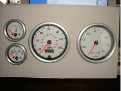 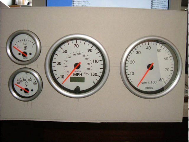
Rescued attachment gauges.jpg
|
|
|
|
|
stevebubs
|
| posted on 18/2/05 at 12:44 AM |
|
|
You could try putting the magnets or whatever on an electric drill rather than spin the rear wheels fruitlessly
(you have configured the pulses per second, haven't you?)
Electronic speedos should read fine below 15mph
|
|
|
indykid
|
| posted on 18/2/05 at 12:55 AM |
|
|
i thought of that, but i cant get the supergue cracked off the diff flange.
the pulse per second are set by the dip switches, set according to the literature that comes with the gauge.
cheers for the input, will have a fiddle tomorrow, and check continuity across the multiplugs.
hope it sorts itself out
tom
|
|
|
Hellfire
|
| posted on 18/2/05 at 01:03 AM |
|
|
Not that I understand independant speedo's but I had a similar problem with the bike clocks.
Basically - you need one feed, one return to clock and another to earth. It needs the earth to give it an open circuit then when it's closed it
returns to clock - this generates your square wave which powers the clock. If you understand that you're a better man than I

|
|
|
zetec
|
| posted on 18/2/05 at 07:43 AM |
|
|
I've got my car up on stands, I'll run it in gear today and see when my speedo starts to indicate.
|
|
|
SteveO
|
| posted on 18/2/05 at 09:45 AM |
|
|
Hiya,
I had the same problem and got in touch with the manufacturers and they said to use only one or two magnets, re-adjust the dip switches and you
should be fine.
Make sure the dip sw are correctly read. the old data sheet the switch 10 starts from left to right and i think the new ones are from right to left or
something like that.
Steve
|
|
|
mookaloid
|
| posted on 18/2/05 at 11:05 AM |
|
|
When I set mine up the (with the wheels off the ground) the speedo stayed on zero on idle and hardly read anything at all when revved up. I adjusted
the pulse rate setting then it all worked fine.
Cheers
Mark
|
|
|
indykid
|
| posted on 20/2/05 at 09:42 AM |
|
|
why don't they tell you exactly what you need to know in the instructions!
so, i started yesterday by checking the loom for continuity, again. all was good, beeped when the reed switch put next to magnets. then i looked at
the destructions, the first page of which contradicts the second about dip switch settings, so i reversed the dip switch settings, and nothing.
i then chipped 2 of the magnets off, re calibrated the switches, and, you guessed it, nothing.
so untaped the loom at the back, and went through the unused wires, at which point i remembered a mental note, about a red wire. double checked wiring
diagram, and it was a 12v pull up (if required), that i had meant to leave open to check once the loom was finished but managed to get heat shrinked
up. BUGGER
connected it to the feed, fired her up, and yes, it worked first time , all the way to 90 in 5th, scary when the wheel is a foot away from your
left ear, i'll tell you. , all the way to 90 in 5th, scary when the wheel is a foot away from your
left ear, i'll tell you.
like a pig in its own faesces i was!
on to the next battle now i suppose
cheers for all the suggestions
tom
|
|
|
Hellfire
|
| posted on 21/2/05 at 12:37 PM |
|
|
Result then - nice one!
|
|
|