dblissett
|
| posted on 22/11/05 at 06:27 PM |

|
|
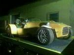
radical s3 dash
i have just bought this off ebay i took a bit of a punt on it
but it seems to have all the displays i need only problem is how to wire it up does anyone have any info or experence with these
i have been on the radical web site and down loaded the manual but its only a user manual without wiring diagrams
thanks dave
[Edited on 22/11/05 by dblissett]
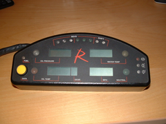 
Rescued attachment Dscf0022.jpg
|
|
|
|
|
serendipity123
|
| posted on 22/11/05 at 06:28 PM |
|
|
seen that before lol
|
|
|
dblissett
|
| posted on 22/11/05 at 06:35 PM |
|
|
lol
i do like a challange
if i wanted it easy i would'nt of started a locost he he
|
|
|
Avoneer
|
| posted on 22/11/05 at 06:36 PM |
|
|
Is the back a multi plug?
If so, are the pins numbered in anyway?
Pat...
No trees were killed in the sending of this message.
However a large number of electrons were terribly inconvenienced.
|
|
|
dblissett
|
| posted on 22/11/05 at 06:55 PM |
|
|
pin numbers
i have taken the back off and there is a terminal board with fifteen screw conectors numbered 1 to 15
|
|
|
rayward
|
| posted on 22/11/05 at 07:08 PM |
|
|
hi,
it was me you bought that from,i had a quick look and couldn't get a diagram for it+changed to using a car engine in mine, so wasn't
really suitable anyway.
good luck with it
Ray
|
|
|
Danozeman
|
| posted on 22/11/05 at 07:08 PM |
|
|
didnt big_wasa get one of them?
Dan
Built the purple peril!! Let the modifications begin!!
http://www.eastangliankitcars.co.uk
|
|
|
Avoneer
|
| posted on 22/11/05 at 07:20 PM |
|
|
Right, now you have the numbers, drop Radical an email and ask if they can give you the wiring diagram or legend for the numbers.
Pat...
No trees were killed in the sending of this message.
However a large number of electrons were terribly inconvenienced.
|
|
|
rayward
|
| posted on 22/11/05 at 07:38 PM |
|
|
I emailed Radical Pat, they never replied
Ray
|
|
|
big_wasa
|
| posted on 22/11/05 at 08:21 PM |
|
|
Its going round the forum
Small world init
regards warren
[Edited on 22/11/05 by big_wasa]
|
|
|
tks
|
| posted on 22/11/05 at 08:28 PM |
|
|
trial and error...
send it to me and i will work it out for you.
Its easy! even because 99% of the thing you know what to do with the pin to get an reaction of the board..
Tks
The above comments are always meant to be from the above persons perspective.
|
|
|
Avoneer
|
| posted on 23/11/05 at 12:47 AM |
|
|
Try emailing some radical owners and see if they have a manual.
Pat...
No trees were killed in the sending of this message.
However a large number of electrons were terribly inconvenienced.
|
|
|
DarrenW
|
| posted on 23/11/05 at 09:30 AM |
|
|
Is it possible to work out which are the main live and earths. After that i would have thought some of the pins are straight forward live inputs to
make a light etc work.
Do you have a power probe? Its poss to seperate the lives and earths with one of those.
Id guess the tricky inputs will be the revs, speed etc (ie the variable inputs) but even these shouldnt be too difficult as i would guess they are
just fed with variable voltage from the sensors - putting in 12V should give max readings.
As always - usual disclaimers apply.
|
|
|
Avoneer
|
| posted on 23/11/05 at 10:54 AM |
|
|
Can you take a good photo of the inside board and we can all have a nosey and see what we can work out.
Pat...
No trees were killed in the sending of this message.
However a large number of electrons were terribly inconvenienced.
|
|
|
dblissett
|
| posted on 23/11/05 at 04:52 PM |
|
|
photo
here is the photo
the pcb has radical dash board pcb606 iss4 on it
above the conection block the orange thingies i dont know what they are
anyway they are marked from left to right s2 s3 s1 s6 s4 s5 s7 s8 s9 s10 s11 s12 s13 s14 f1
f1 is not the same as all the other thingies its yellow and more of a round shape
sorry for the crap descriptions but i am not into electronics
but i have a feeling i am about to learn
cheers dave
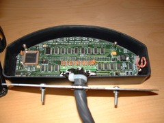 
Rescued attachment Dscf0025.jpg
|
|
|
DarrenW
|
| posted on 23/11/05 at 05:00 PM |
|
|
It might be worth getting a close up of the plug / connection area. Can you also indicate on the pcb area what is on the other side? (ie where warning
lights and gauges are etc).
What the boffins will try and do is follow the pcb tracks to a specific area or light etc to try and eliminate some of theeasy ones.
The trick is to find the main live and earth. This should power the dash up. From there some of the other terminals can be tested. Im not sure if they
will take a full 12V input or 5V from the engine bay sensors.
|
|
|
DarrenW
|
| posted on 23/11/05 at 05:02 PM |
|
|
Try also looking for some special codes etc and do a search on internet. If you hit lucky you might find the circuit diagram or maybe the manufacturer
who might be more willing to help.
|
|
|
tks
|
| posted on 23/11/05 at 08:26 PM |
|
|
OK lets start!
I can already tell you wich is live and wich is ground.
You see the Voltage ragulator?
The big black humb?
His chasis is always ground (99% of cases)
soow take the polimeter and start bleeping the pins again that chasis.
The one you find is Earth.
2) if you take the left pin from the three looking from above. and pins in down direction. that the voltage feed!
search between that pin and another small one and you have voltage feed!
now i need better pics to say more.
Tks
test it anyway with the conector you see.
on the right one of the pins need to be earth. Don't fool you if it goes to another small pin, because maybe its the backlight wich you connect
to your lights of the car..
also look at the black lump the code on it tells you if it is an voltage regulator and how much it is.
if it has xx78xx in his name it is one 100%.
make an closeup.. anyway of it.
[Edited on 23/11/05 by tks]
[Edited on 23/11/05 by tks]
The above comments are always meant to be from the above persons perspective.
|
|
|


%20(WinCE).JPG)