whittlebeast
|
| posted on 6/9/06 at 02:36 AM |

|
|
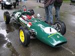
A strong chassis
I am starting to design a new chassis based on the basic dimensions of a Locost but I plan on installing a 425 hp 4 LB-FT LS1 A little underpowered,
but I want reliability for the street. This chassis is about 4 times stronger in torsen than a standard Locost per grape FEA. Note that this chassis
does not rely on stressed panels for strength, Any helpful thoughts would be great.

AW
[Edited on 7/9/06 by whittlebeast]
|
|
|
|
|
ADD
|
| posted on 6/9/06 at 07:02 AM |
|
|
Hi and welcome,
Looks pretty substantial to me, but you dont show a transmision tunnel, I rigid tunnel will improve chassis stiffness agreat deal as well, also some
well placed welded bulkheads will also improve stiffness.
Also, with using a large engine and the associated running gear I would suggest some strength in the mounting points.
Adam
|
|
|
chrisj
|
| posted on 6/9/06 at 07:11 AM |
|
|
Running a small block chevy in my Luego. When we were putting the chassis together extra triangulation went in everywhere to the extent where an extra
7 m of tubing went in.
The engine mounts were easy we got them from a hot rod place. They're rated to 1000 hp and as a result the car rocks not the engine !
Will be at Donnington if you want to cast your eye over the extra triangulation.
|
|
|
Danozeman
|
| posted on 6/9/06 at 08:17 AM |
|
|
Are you making one with a roof??
Dan
Built the purple peril!! Let the modifications begin!!
http://www.eastangliankitcars.co.uk
|
|
|
MikeRJ
|
| posted on 6/9/06 at 08:27 AM |
|
|
What's happened to the side diagonal at the rear (can't remember tube name off hand, the one in red). On a standard locost chassis I reckon
that would be a fairly important chassis member as a lot of the rear suspesnion forces would be directed down it.
Locost Chassis Design
Are you going to be able to get in and out ok with the roll cage design?
|
|
|
iank
|
| posted on 6/9/06 at 08:50 AM |
|
|
Best thing to do now is to build a balsawood model (available in thin square section from model shops, hot glue gun works well). Stick on some thin
card (or plastic card if you're feeling flush) for any structural bulkheads.
Then you will find out how it actually performs, just grab it by the suspension mounts and twist gently, soon feel and see any weak points.
A good 3d model rather than a picture is also much better for deciding if it's practical and good looking - getting in and out, exaust headers,
getting the engine in and out etc.etc.
|
|
|
JamJah
|
| posted on 6/9/06 at 09:08 AM |
|
|
iank, your sounding like my architecture lecturers! but very true, an old coat hanger, pairof pilers and a scale rule on the next shopping list!!!
whittlebeast, you have triangulation across your passenger compartment in the form of a roll cage(?). wont this make it hard to get in??
|
|
|
whittlebeast
|
| posted on 6/9/06 at 01:57 PM |
|
|
This car is going to be an autocross car and possibility licensed for ocational use on the street. Entry thru the roof or thru the side (and the
small hole in the cage) is an option. Regarding motor mounts, I may just build a front and rear mounting plate and let that structure serve as the
firewall bulkhead. I have built several cars and I always use Grape FEA to design the structure. see photos of my last car at
http://www.ncs-stl.com/racecar
FEA software is at
http://www.grapesoftware.mb.ca/
I have tube definition file for anyone that wants to do chassis design
AW
[Edited on 6/9/06 by whittlebeast]
|
|
|
JamJah
|
| posted on 6/9/06 at 03:18 PM |
|
|
As you as you know what your doing! hehe.You probably know far more than me by the sounds ofit. Personally I'd still mock up certain sections at
scale. Id also probably be tempted to mockup the rollcake in cardboard tube just to see whether its quick to escape in an emergancy.
Sorry I didnt mean to sound like i was doubting you, just id prefer to ask and be told to shut up rather than not ask and you get stuck a few
monthsinto the build or anything worse when running at speed.
|
|
|
whittlebeast
|
| posted on 6/9/06 at 03:59 PM |
|
|
JamJah
No problem. Generally I start with the basic triangulation of the chassis an prove that the basic concept is do-able. I next get the large
components that are difficult to move like engine transmision and differential on the floor and mark the outline of the chassis and all major
bulkheads to make shure I still fit in the big picture. In this cas I have the luxury of setting in existing cars and hold a peoce of tubing in about
the location that the model FEA is showing to prove that I can fit my knees in the chassis and I can get thru the holes that I think will work. In
sitting in an existing car I soon realized that my hips, knees and the center box structure were in conflict when I got the motor back far enough.
This thing is slated for a powerglide transmission as I plan on it being fas enough that the last thing I want to think about is 5 or 6 gear changes.
(I also own a shifter kart so...)
see http://www.ncs-stl.com/mike/Mike_Gateway_Spin.wmv to get an idea how fast these cars are.
AW
|
|
|
whittlebeast
|
| posted on 7/9/06 at 11:16 AM |
|
|
Here is and interesting option for a high HP install out of a 2000 Ford Cobra.


[Edited on 7/9/06 by whittlebeast]
|
|
|
whittlebeast
|
| posted on 8/9/06 at 02:56 AM |
|
|
I think I have desided to use the old racecar rear suspension. All I have to do is locate an old Nissan rear dif to mount in the center of it and
redesign the mount. This way I own the wheels front and rear.

The front suspension will most likely be...

[Edited on 8/9/06 by whittlebeast]
|
|
|
whittlebeast
|
| posted on 10/9/06 at 02:44 PM |
|
|
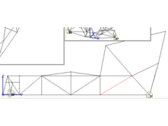
Just for fun, I did some anyalizing of the basic locost chassis this weekend Here is the results.
green panels as stressed members 938 ft-lbs/deg (note that the center tunnel is stressed on all four sides but is a little hard to present the lower
picture showes the tunnel better)
green panels as stressed members plus added red braces 1780 ft-lbs/deg
green panels as stressed members plus added red braces plus blue panels 2000 ft-lbs/deg
my chassis with no center tunnel and no stressed panels at all but with a full cage 9320 ft-lbs/deg
As a general rule of thumb is you take the weight of the car with driver and fuel in lbs times 3 to get the minimum strenght required to get
theshocks springs and anti-roll bars to do their job. so a 2000 lb car should have about 6000 ft-lbs/deg stiffness Just a little food for thought

Andy


[Edited on 10/9/06 by whittlebeast]
|
|
|
MikeRJ
|
| posted on 10/9/06 at 03:56 PM |
|
|
If you are going by the book there is still a diagonal missing between H and A1.
Previous analysis has shown that putting another R tube in on the other side of the engine bay, and triangulating the LA,LB,LC,LD stucture is very
benficial. Would be interesting to see if your model supports this.
|
|
|
whittlebeast
|
| posted on 10/9/06 at 04:39 PM |
|
|
I tried adding the H - A1 tube but there was very little added strength. I was trying to add as little as possible to get the largest BANG for the
added weight and complexity.
The front most bulkhead was not moving around that much.
AW
[Edited on 10/9/06 by whittlebeast]
|
|
|
whittlebeast
|
| posted on 10/9/06 at 08:48 PM |
|
|
MikeRJ
I added the blue tube and got up to 2400 ft-lbs/deg The tube is in addition to all the other mods, the 4 side tubes and the two roll cage stressed
skins.
Remember that attaching these skins to support these sort of loads may take some effort. I try to stay away from stressed panels. They tend to be a
fabrication and maintaince nightmare. I avoid drilling any holes into tubing as I like to vent every tube into another tube so that they are all
innerconnected. That way I can pressurize a chassis and check for hidden cracks with age.
AW
|
|
|
locostv8
|
| posted on 10/9/06 at 09:30 PM |
|
|
It would seem that the driveshaft tunnel, firewall, bulkhead, and outer skin would add considerably to the overall strength turning the frame into a
Monique. I agree with drilling the tubing from a structural point of view. I plan on using 16 ga steel for all sheet with 18 ga steel used for the
outside panels. These are simple flat panels and not difficult to fab. The plan is to full weld the perimeters with skip weld and fill weld to
interior tubes. The whole assembly to receive a light coat of linex to seal and provide additional bond. A cage such as the Westy will be welded in.
I'm building for 500 hp.

[Edited on 10/9/06 by locostv8]
[Edited on 11/9/06 by locostv8]
http://wrangler.rutgers.edu/gallery2/v/7slotgrille/hssss/
|
|
|
whittlebeast
|
| posted on 10/9/06 at 11:19 PM |
|
|
LocostV8
Cool cage. The problem with seam welding in the panels is all the heat that gets applied to the chassis. I have had better luck sticking with tubes
and for the most part square sections except where the actual roll structure is involved.
At some point I reach too much strength and start removing tubes to simplify the structure any tube that comes up in a blue color and is not there for
some specific reason is removed?
What software are you using to model that cage?
|
|
|
locostv8
|
| posted on 11/9/06 at 03:41 AM |
|
|
Wish I could take credit for the cage but it is a Westfield competition cage. It would be too easy to use modeling software but it takes $$$ and
I'm retired so I try to stick somewhat close to what is known to work.
I'm going a bit overboard with the first LC and using 1x1.5x11ga for the main rails and 1x1x14ga for the .75 x.75x16 ga. If you stitch weld in
short sections and go back several times to fill in you minimize the heat applied. In doing this I'm going overboard but am turning the entire
structure into a cage. This will be a street car using a roller 392(351) with efi, T5, and MN12/Cobra (MII geometry with longer A arms and Rorty rear
with appropriate mods) suspension pieces and a budget of about 3k (with stock roller 351).
It appears you are into EFI, I would be greatly interested in talking offline about it.

Deman MN12 IRS

R/H 2000 Cobra R Center Explorer L/H MK VIII with explorer back cover
I will be using the Cobra R housing with Torsen T2(OEM) and Explorer cover giving 4 point mounting for the diff
[Edited on 11/9/06 by locostv8]
http://wrangler.rutgers.edu/gallery2/v/7slotgrille/hssss/
|
|
|
whittlebeast
|
| posted on 11/9/06 at 10:30 AM |
|
|
LocosttV8
Just go over to http://www.msefi.com and post a question. We can Squirt anything Just get a signon of locostv8 and I will realize it's
you.
AW
[Edited on 11/9/06 by whittlebeast]
|
|
|
cymtriks
|
| posted on 15/9/06 at 09:27 PM |
|
|
FEA
My FEA results have already been posted on this site.
The book chassis has 1180 ftlbs per degree and weighs 181 lbs.
Adding a V brace on the front face and diagonals across the front suspension mount tubes is a very worthwhile improvement. Another is to weld in the
panels on the top of the tunnel and at the bottom of the front suspension region.
Some of the tubes in the tunnel do very little and can be left out.
Some more weight can be saved by making the panels in 18 gauge as opposed to 16 gauge.
The result is 2541 ftlbs and a weight of 171 lbs.
Replacing tube R with a Y brace on each side of the engine bay gives 2683 ftlbs for 174 lbs weight.
This final modification results in a chassis that is ten pounds lighter than the book design and has just two extra tubes in total.
Look up kitcaranalysisv2.doc (version 2) for a full description of the mods.
If anyone would like a Nastran input deck I'll be happy to email it to them.
|
|
|
Peteff
|
| posted on 15/9/06 at 09:40 PM |
|
|
I can't see where you are going to fit the engine in with all the engine bay bracing. The support at the front of where the tunnel goes will
obstruct your gearbox bellhousing unless I am looking at it wrong.
yours, Pete
I went into the RSPCA office the other day. It was so small you could hardly swing a cat in there.
|
|
|
whittlebeast
|
| posted on 16/9/06 at 02:15 AM |
|
|
The tube over the bell housing has been raised a few inches to allow for the large motor. The final location of the four engine bay braces will be
determined once the motor is in place. If I have to I can stress member the motor.
(yep americans interchange motor and engine. Nobody calls them enginecycles)
cymtriks
I was looking for 6000 ft-lbs / deg and wanted to avoid stressed panels if possible.
AW
[Edited on 16/9/06 by whittlebeast]
|
|
|
whittlebeast
|
| posted on 18/9/06 at 02:35 PM |
|
|
I have managed to get to 12000 ft-lbs/deg with a design that all of the lower frame rails are in book locations. The roll cage is situated in a way
that the driver can get in and out without any real issues. The entire center tunnel structure is not required. It is all possible to do.
Now I feel confident that a suspension can be designed to realy handle as a new Lotus handles. I am designing to a 1850 lb minimum weight so I am
hoping to have to add about 500 lbs of steel to the floor and get the weight distribution where I need it to accelerate as required. There should be
room to add a turbo where the normal passengers feet go as there is no tubing there now if 400 HP ends up controlable.
Just a little food for thought.
AW
[Edited on 18/9/06 by whittlebeast]
|
|
|
DIY Si
|
| posted on 18/9/06 at 05:42 PM |
|
|
1850 lbs? Crikey that's heavy. Why so much? Or does all the strenghening and engine of choice make up most of this?
Let your plans be dark and as impenetratable as night, and when you move, fall like a thunderbolt.
Sun Tzu, The Art of War
My new blog: http://spritecave.blogspot.co.uk/
|
|
|