davimora
|
| posted on 9/9/03 at 10:35 AM |

|
|
front assembly jig for dummies...
what's the best way for build a jig for the 'L' front assembly?
I built mine... without success.. 
Regards,
Davide
[Edited on 9/9/03 by davimora]
|
|
|
|
|
kingr
|
| posted on 9/9/03 at 10:48 AM |
|
|
Do you mean La,Lb and so on? If so, simply clamp the bottom piece to your work bench, get 3 pieces of 25mm tube and stack them up, put the top tube on
top of them and clamp it to your work bench so that it's parallel, and symetrical. Then lay the two compound angled bits in place and carefully
tack it all up.
Kingr
|
|
|
davimora
|
| posted on 9/9/03 at 11:00 AM |
|
|
Is exactly what i did, but i think i measured something wrong. I'll retry the next weekend.
Thank you very much,
Davide
|
|
|
James
|
| posted on 9/9/03 at 01:18 PM |
|
|
quote:
Originally posted by davimora
Is exactly what i did, but i think i measured something wrong. I'll retry the next weekend.
Thank you very much,
Davide
I made mine out of chipboard and wood screwed together. If I get the camera back soon I'll try to get some pics for you.
James
|
|
|
Hornet
|
| posted on 10/9/03 at 08:06 AM |
|
|
Remember the book dimensions are wrong for this... 
|
|
|
burgessj
|
| posted on 10/9/03 at 09:20 PM |
|
|
Have a look at Mark Allanson's photo archive...
There's a good photo of the front assembly...
Hope it helps
JohnB
|
|
|
Mark Allanson
|
| posted on 10/9/03 at 09:22 PM |
|
|
If you want any other photos of different angles etc - I have over 600 of the build so far!!
|
|
|
Alan B
|
| posted on 11/9/03 at 03:28 AM |
|
|
Bloody slacker...
I have over 2000......
(yeah I know....sad.....)
|
|
|
I love speed :-P
|
| posted on 26/3/04 at 07:07 PM |
|
|
sry 2 bring this up again but, i have just made the jig which has come out well, however no matter what i do i can not get the "two compound
angled bits" at the right angles.
does any1 no a good way of getting the angles or something which along these lines
Thanks 4 ur time
Philip Moreton
Don't Steal
The Government doesnt like the competition
|
|
|
MikeP
|
| posted on 26/3/04 at 07:19 PM |
|
|
Mike Laws has built a bunch of these cars, he builds the L assembly flat, mitering the longer chassis rails (J1&2, F1&2) to lean the L section
at the proper angle.
|
|
|
JoelP
|
| posted on 26/3/04 at 08:21 PM |
|
|
quote:
Originally posted by I love speed :-P
does any1 no a good way of getting the angles
the best tool for compound angles in my opinion is a rotary cutter, like a big grinder on a stand. You can then set on angle with the bar and the
other angle on the grinder. Machine mart do a selection of these.
trouble with a band saw like i have is it can only do one angle and the damn blade never cuts straight
Beware! Bourettes is binfectious.
|
|
|
NS Dev
|
| posted on 27/3/04 at 12:30 AM |
|
|
It was a few years ago that I built my first locost chassis (I'm buying one this time!) and the dimensions for this bit are completely wrong,
which threw me when I dew it up on CAD and made a nice jig, only to find it didn't fit the car!!
|
|
|
jcduroc
|
| posted on 28/3/04 at 02:37 PM |
|
|
quote:
Originally posted by Alan B
Bloody slacker...
I have over 2000......
(yeah I know....sad.....)
That's the reason why your build is not yet finished (I guess)
João
JCM
|
|
|
Jayce Lane
|
| posted on 30/3/04 at 07:58 AM |
|
|
Seeing that the dimensions are wrong, can somebody enlighten us on what they should be. I started work on the front last night, and all looks good so
far!!! Am I missing something
|
|
|
Peteff
|
| posted on 30/3/04 at 08:41 AM |
|
|
If you make the front and the top wishbones to the book dimensions you will not get the castor angle of 5.? degrees without almost missing the fu
section with the top rear bracket. I am in the process of making a chassis with the front altered to rectify this and have moved the lb and fu rail
back another 25mm and altered the width of the bottom wishbone to suit.
[Edited on 30/3/04 by Peteff]
yours, Pete
I went into the RSPCA office the other day. It was so small you could hardly swing a cat in there.
|
|
|
Jayce Lane
|
| posted on 30/3/04 at 08:49 AM |
|
|
Hi Pete,
Wont it just be easier to build the nose as per book and move fu1 and fu2 to fit the suspension. Just an idea if you view the thread on concern of
front suspension. Looks like a couple of the guys have gone that route?
|
|
|
Peteff
|
| posted on 30/3/04 at 09:03 AM |
|
|
You could, but if the top wishbone is made to the book design then you will almost miss the front bracket instead of, or as well as, the rear one. I
found it easier to work out and with my latest efforts I can make a simple jig out of threaded and flat bar to locate the brackets and get the angle
right on both sides.
yours, Pete
I went into the RSPCA office the other day. It was so small you could hardly swing a cat in there.
|
|
|
Jayce Lane
|
| posted on 30/3/04 at 10:22 AM |
|
|
Pete,
In deviating from the book in terms of the bottom wishbone, do you know of any unwanted side effects, and have you remained with the book measurements
for the top wishbone, or has this also been adapted.....
Secondly in constructing the nose, what has been the horizontal distance from lc to ld you have used, as this distance determines the angles?
|
|
|
Bob C
|
| posted on 30/3/04 at 10:33 AM |
|
|
I've just been here....
I downloaded Macsorley's plans & had NO problem building using them. To put front suspension points on I used a simple jig, tacked lower
rears in place then fixed FU tubes to pick up upper rears nicely.
I then removed LA and LB (very front uprights) and retacked these with the front pickups in place & tacked them on too. The uprights had to move
in a bit.
This was all pretty straightforward once the jig was made. I repositioned the lower 10mm further forward of upper to correct castor. Check front
suspension jig pics in photo archive of "Bob C" to see how I did it - it may give you some inspiration (or not....)
Cheers
Bob C
|
|
|
Peteff
|
| posted on 30/3/04 at 12:43 PM |
|
|
I put an extra piece of rhs under the top rail to make it 25mm further back. I have altered the top wishbones from the book and am in the ongoing
process of jigging it. My rear bottom wishbone bracket is behind the fu section so the jig would not work with a bar through both at once
[Edited on 30/3/04 by Peteff]
yours, Pete
I went into the RSPCA office the other day. It was so small you could hardly swing a cat in there.
|
|
|
Peteff
|
| posted on 30/3/04 at 03:39 PM |
|
|
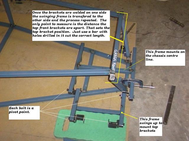
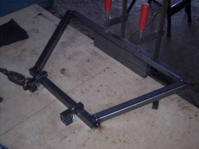
I forgot to put in that my chassis is 1" taller as well, sorry, so it slightly lessens the effect of putting the top la section further back. So
far this is what I've made for the suspension jig out of flat bat and threaded tube. I need a piece to join the rear suspension brackets together
and set them at the same distance as the front ones. The insides of the bottom wishbone brackets line up with the outside of the top ones and the
castor angle should come out as a result (if my design works)
Rescued attachment frontjig.JPG
yours, Pete
I went into the RSPCA office the other day. It was so small you could hardly swing a cat in there.
|
|
|
Jayce Lane
|
| posted on 31/3/04 at 06:12 AM |
|
|
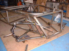
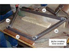
Chatting to some local boys, they have follwed the book really, and in creating their jig, they have raised Lc to 76mm to get the right angles for La
and Lb. Which is absolutely in line with McSorely's drawings. The postioning of FU1 and FU2 should be best left till a suspension jig has been
made as the attached photo, from a bloke in Australia. Hope that this helps all those who were initially baffled as I.
Rescued attachment Jig for front suspension.jpg
|
|
|
britishtrident
|
| posted on 31/3/04 at 06:40 AM |
|
|
quote:
Originally posted by kingr
Do you mean La,Lb and so on? If so, simply clamp the bottom piece to your work bench, get 3 pieces of 25mm tube and stack them up, put the top tube on
top of them and clamp it to your work bench so that it's parallel, and symetrical. Then lay the two compound angled bits in place and carefully
tack it all up.
Kingr
I did much the same taking a great deal of care to get all the angles as near correct as I could, To get it absolutely correct I did some adjustment
by heating and ever so slight bending.
|
|
|
Jayce Lane
|
| posted on 31/3/04 at 07:50 AM |
|
|
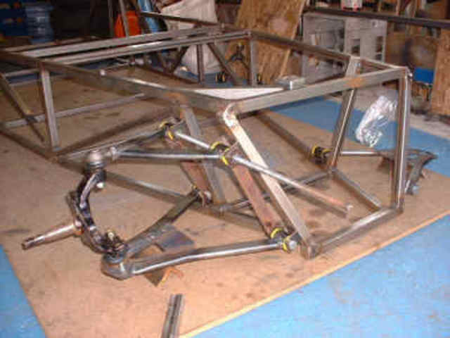
Hi davide
I have attached a photo of a Jig for using on the front assembly as per my brief description previously.
Cheers
Jayce
 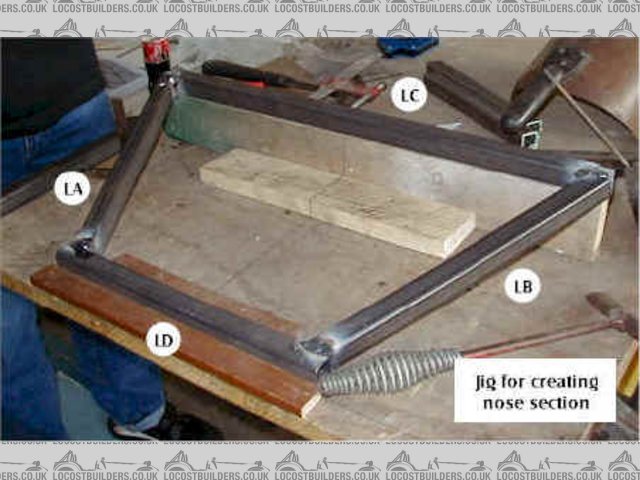
Rescued attachment front Jig.jpg
|
|
|
Mark Allanson
|
| posted on 31/3/04 at 07:52 PM |
|
|
... very similar, but less tree wood!
Rescued attachment FrontPanel.jpg
If you can keep you head, whilst all others around you are losing theirs, you are not fully aware of the situation
|
|
|