bigandy
|
| posted on 11/11/07 at 05:32 PM |

|
|
4a-ge cooling and exhaust questions
Evening all.
I was wondering if anyone can help with any of the following questions I am strugglingto find an answer for?
1. Are the exhaust ports on the 16v 4a-ge the same size/layout as those on the 20v 4a-ge variants? I am fitting a 16v engine to my car to begin
with, but I am toying with the idea of saving some money to fund a 20v engine in the future.
2. Does anyone know where I might be able to find a clear diagram/explanation as to exactly how the 4a-ge cooling system is designed to be connected
up? All I can seem to find is a few fuzzy gif images, none of which really resemble to engine I have in my garage!
Cheers
Andy
Dammit! Too many decisions....
|
|
|
|
|
ghuncha
|
| posted on 11/11/07 at 05:59 PM |
|
|
the exhaust fastenign bolts are different only
with some welding and drilling you can fit a 16v in 20v...
|
|
|
COREdevelopments
|
| posted on 11/11/07 at 09:30 PM |
|
|
i have a toyota workshop manual. and iirc it has a diagram of the waterflow in the cooling system, i will try and get it uploaded for you.
and ghuncha is correct ther is only one flange hole difference, as i was supplied a 20v system when i ordered a 16v system from tube engineers.
rob

|
|
|
bigandy
|
| posted on 11/11/07 at 10:07 PM |
|
|
Hi Rob, that would be great if you could upload a picture of the cooling system plan from a manual, I'll have to owe you a beer!
Regarding the one hole location difference between the 20v and 16v, if I were to make up an exhaust flange, could both holes be included in the
flange, allowing the manifold to fit both variants? Or are they too close together to do something like that?
Cheers
Andy
Dammit! Too many decisions....
|
|
|
COREdevelopments
|
| posted on 11/11/07 at 10:13 PM |
|
|
if i dont upload one by tues night please u2u me. as for exhaust iirc the no 4 exhaust port end bolt is the only difference. the 20v type is more
spaced out than the 16v one. i did have pics of it as i took some to send to tube engineers. i will try and find them for you, unless i may of deleted
them.
hth
rob
|
|
|
rick q
|
| posted on 11/11/07 at 11:10 PM |
|
|
There's a bit on the cooling systems here :- http://www.geocities.com/MotorCity/Garage/8422/4age.htm and a bit more here :-
http://home.clear.net.nz/pages/phil.bradshaw/Engine%20Installation.htm#20%20Valve
The 20Valve and 16Valve exhausts can be made to swap with a few changes to the outside bolt holes on the 16 valve to make it fit to the 20 valve - a
couple of comments here :- http://www.oz-clubbies.com/forums/index.php?showtopic=7049
|
|
|
Findlay234
|
| posted on 12/11/07 at 07:53 AM |
|
|
As for 16v cooling heres a diagram of the engine block water flow. I used this and developed my own cooling system.
Where does you engine come from. This is fairly important if you have all the cooling ancils. I used the thermostat from an mr2 which is seperate to
the engine while the corolla one i have mounts onto the water pump. Not really important just affects the design of the system.
Rescued attachment 4agwater.gif
|
|
|
Findlay234
|
| posted on 12/11/07 at 07:55 AM |
|
|
I have different coolant attachments on my engine but it gives you an idea about where you want to connect the pipes to.
|
|
|
Jos Fury
|
| posted on 12/11/07 at 03:26 PM |
|
|

|
|
|
Jos Fury
|
| posted on 12/11/07 at 03:30 PM |
|
|
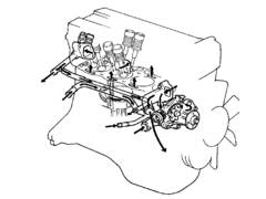
Above is my 4age. The red hoses are added. The lower one to improve flow at cilinder nr.4. the upper one I am still testing. ( this one is meant to
get the air out of the highest point to the expansion tank )
The black spot on the left is the expansion tank. the grey spot is my thermostat housing.
from the thermostat one hose goes to the engine but is not visible on the pic. therfore it is blue and marked like . . . . . .
sorry for the bad pic and ugly drawing 
and of course thanks to Thomas Rouw who explained me a lot about the cooling system !
[Edited on 12/11/07 by Jos Fury]
[Edited on 12/11/07 by Jos Fury]
|
|
|
bigandy
|
| posted on 17/11/07 at 11:06 AM |
|
|
Hi folks,
Thanks for the input so far. I've spent a bit of time figuring out what goes where, and I think I am nearly there now!
One thing I am wondering though, is which direction the water pump, er, pumps? Does it force water into the engine block? I think it is that way
around, especially if the Thermostat lets cool water into the block as described on some of the links posted so far.
As I am not planning to fit a heater, I was wondering what to do with the heater connections on the various parts. Is it best to blank these off, or
just connect them together (as if the heater was there, just without the heater matrix and miles of hoses!)?
Finally, I am wondering about a header tank and radiator "cap". There are two 8mm pipe connections on the various parts of my engine, and
I am thinking these are the ones that need to be routed to the header tank. One of these is located in the hose that comes from the waterpump, so
depending on which way round the pump, er, pumps, this will need to go to the header tank inlet, or outlet.
Cheers
Andy
Dammit! Too many decisions....
|
|
|
COREdevelopments
|
| posted on 18/11/07 at 12:38 PM |
|
|
this is the only pic i could find really. its for an ae92 which is the fwd version corolla not the rwd ae86. only difference is the thermostat
housing..JPG)
|
|
|
bigandy
|
| posted on 18/11/07 at 01:08 PM |
|
|
Thats great cheers Rob.
If my eyes don't deceive me, the waterpump connection is letting water into the pump.
I think I've got it all sorted now, with the exception of the header/expansion tank. I'm going to have do a bit of reading up on the tank
design, to see what needs to connect where for that. I have two 8mm connections, one in the "water inlet pipe" and one in the thermostat
bypass pipe, which is the one feeding into the "to radiator" head connection in the above diagram.
Cheers
Andy
Dammit! Too many decisions....
|
|
|
bigandy
|
| posted on 26/11/07 at 09:27 AM |
|
|
Just for completeness, I had a look under the engine cover of an MR2 over the weekend. The expansion tank is a very simple affair, and simply takes
the overflow outlet from the filler cap (located in the top hose near the engine) and feeds it into the expansion tank (pipe to the bottom of the
tank, via the normal sealing cap).
There is a vent line at the top of the tank. and also an additional line that is connected to a bleed valve on the thermostat housing (towards the top
of the tank).
Cheers
Andy
Dammit! Too many decisions....
|
|
|