RK
|
| posted on 6/5/08 at 01:29 AM |

|
|
making ali rear arches
Rear arches will cost me about $500 or 250 GBP over here. I was thinking of making some from ali sheet, shaped around my wheel, and adding commonly
available universal fender flares on the edges, glued on.
How would they attach to the car, and is this a possibly good idea or not? Trying to save a bit as my costs are very high here in Canada, and
I've needed to hire people for things like electrics, fuel system and turbo intercooler installation.
|
|
|
|
|
speedyxjs
|
| posted on 6/5/08 at 06:26 AM |
|
|
Im also thinking about making my own arches due to the high costs involved. I think your idea is quite a good one 
How long can i resist the temptation to drop a V8 in?
|
|
|
Humbug
|
| posted on 6/5/08 at 06:44 AM |
|
|
It might work - depends on the look you would be happy with.
To attach to the bodywork, I would make a former out of wood the right shape, then cut triangle sections out of the inside edge of the wing, bend the
wing round the former and hammer with a soft headed hammer to make it follow the curve. You could strengthen it by bonding on a piece of curved ali to
hold all the tabs together, then drill through and bolt it on. Crap pic attached
 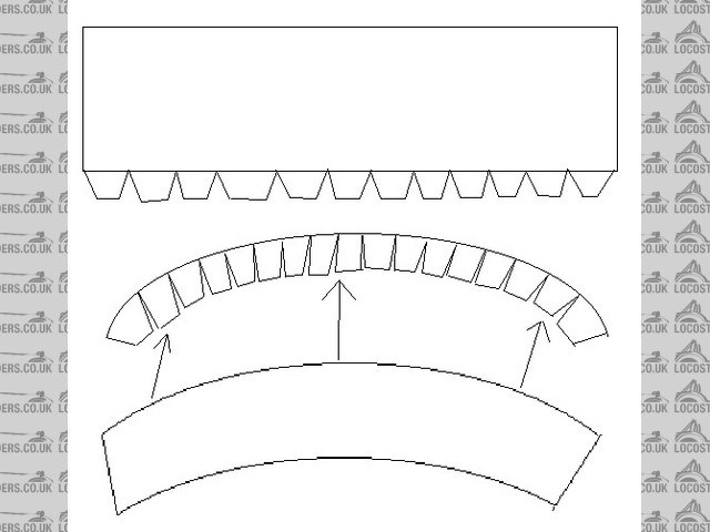
Rescued attachment rear arch.jpg
|
|
|
scutter
|
| posted on 6/5/08 at 07:28 AM |
|
|
Robin hood cars use this method on there lower models, appears to work ok.
Robon Hood cars site
Also Here for the arch edges themselves.
ATB Dan.
[Edited on 6/5/08 by scutter]
The less I worked, the more i liked it.
|
|
|
907
|
| posted on 6/5/08 at 04:36 PM |
|
|
Hi RK,
Firstly I should warn you that metal shaping is addictive. 
Method 1
Make a former from thick plywood ( 3/4" ) the shape you want the arch to end up, plus 2" on the bottom edge.
Cut holes in the former about 1" in from the edge so you can get G clamps in to hold the sheet to the former.
(If you go with this method I'll do you a drawing to explain this better.)
You will be able to knock over a 1/2" edge without needing to cut V's.
Plenty if you fix to the body with 3/16" bolts
The pic below shows my scuttle corner. (5" rad)
By cutting down the width of the flange it was easy to knock the edge over without ripples using a rubber hammer.
I will post method 2 later.
HTH
Paul G
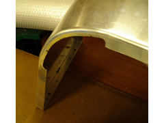 
Rescued attachment scuttle-corner-s.jpg
|
|
|
907
|
| posted on 6/5/08 at 06:14 PM |
|
|
Method 2
Using a shrinker.
Fold a 1" bend on a sheet.
Shrink the inner edge of this flange with the "special tool". (multi pass)
(note the block of rubber glued on the top jaw to space the jaws from the bend)
I payed £80 for the shrinker but I believe they are considerably cheaper in the US.
(don't know about Canada though)
You could always sell it after, but I think you would want to keep it.
HTH
Paul G
Rescued attachment Rear-arches-m-s.jpg
|
|
|
RK
|
| posted on 6/5/08 at 10:25 PM |
|
|
It seriously looks a bit beyond my abilities (which consist of bending a diffuser plate up and over my lower rear horizontal bar at the back). I am
having trouble understanding what you are suggesting. Do you mean a heat gun? I have one of those I use to burn powdercoat into unrecognizable
marshmellows.
I appreciate the ideas in any case! Keep them coming people!
|
|
|
907
|
| posted on 6/5/08 at 10:50 PM |
|
|
quote:
Originally posted by RK
It seriously looks a bit beyond my abilities
Rubbish!
If you can knock nails in without hitting your fingers, then you can bend ally.
The only things people do wrong when knocking an edge over is...
not clamping the metal to something solid, i.e. the former,
and...
trying to move too much metal at once.
I had never done any ally work before I started my bodywork.
Paul G
p.s. throw your heat gun away.
|
|
|
RK
|
| posted on 7/5/08 at 01:47 AM |
|
|
I appreciate your optimism, but I really don't know what you are trying to get at here: what is a former, and what do you bend the ali around to
get a nice neat job like you've done? What clamps to what and where?
|
|
|
907
|
| posted on 7/5/08 at 07:58 PM |
|
|
quote:
Originally posted by RK
I appreciate your optimism, but I really don't know what you are trying to get at here: what is a former, and what do you bend the ali around to
get a nice neat job like you've done? What clamps to what and where?
Hi RK,
Hopefully all will become clear.
A former is, in this case, a simple piece of thick plywood, cut to the shape you want your arches to be.
The arches must clear the tyre, and allow room for the up and down movement of your suspension.
Mine are symmetrical, so the left hand one will fit the right hand side of my car and vise versa.
You could make yours to whatever pleases your eye. The pic below is just a guide.
Cut out the shape carefully and keep the cut edge square. Sand the edge with a block, but don't round the corner. Keep it sharp.
The holes can be any shape. They are just for G clamps. (see next post)
Paul G
 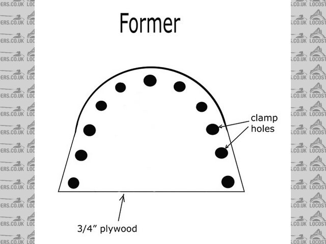
Rescued attachment drw-arch-2-s.jpg
|
|
|
907
|
| posted on 7/5/08 at 08:10 PM |
|
|
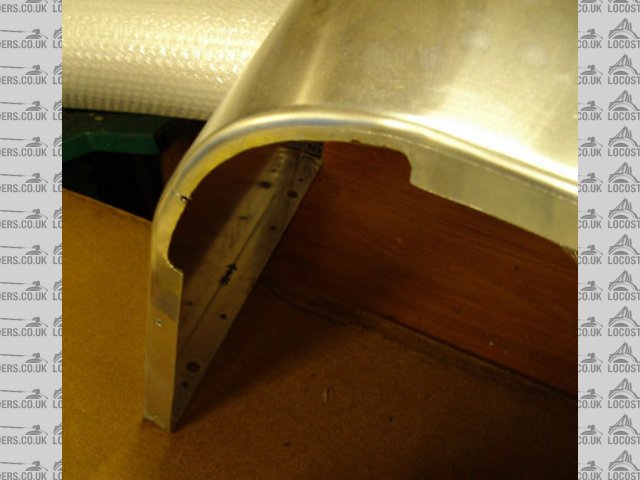
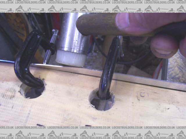
Cut a rectangle of ally and clamp to your plywood former.
It will bend easily around a radius that big.
Allow 1/2" of ally to protrude above the former. This is the edge you will knock over 90 deg.
Pic below shows the clamps holding the ally to the former. In this case just a rough mock up for the camera.
Are you with me so far?
Paul G
Rescued attachment 000_0280-s.jpg
|
|
|
RK
|
| posted on 7/5/08 at 10:46 PM |
|
|
Now I think we're getting somewhere. Ingenious! You are using plywood or whatever, and only attaching the ali to the edge. Neato!
Question: did you use several clamps or can you just move two or three around to the spots you are bending?
|
|
|
907
|
| posted on 8/5/08 at 12:16 AM |
|
|
Yup, Loads of clamps.
Once the edge is formed the arch will stay in shape. Until then it needs to be held tight to the former.
Another way is to run a "ratchet tie down strap" around, then only use a couple of clamps either side of where you are hitting.
(You might call these something different in Canada.)
The important thing is to knock down the flange in stages.
Work along the edge tapping over to 30 deg, then to 60 deg, then to 90 deg.
It can't be done in one pass.
Paul G
|
|
|
RK
|
| posted on 8/5/08 at 02:07 AM |
|
|
Very good! Thank you very much. I feel like I can at least give it a try now.
We call them zip ties (Americans call them zap straps), and they are used extensively in downhill mountain biking to hold on brake lines etc, since
the suspension movement is always knocking them loose.
|
|
|
907
|
| posted on 8/5/08 at 05:06 PM |
|
|
Hi again,
It may pay you to measure the size of the fender flares that you intend to use, then make your plywood former the same radius.
It also pays to use pieces of wood under the feet of clamps so you don't mark the ally sheet.
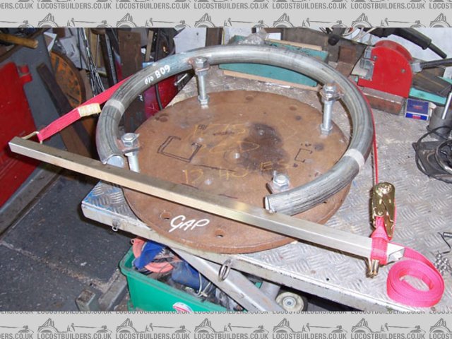
Below is a pic of the jig I used to form the curved outer edge of my arches. Note the red "ratchet tie down strap" that holds
the ally tight to the ring of pipe.
You could use a similar strap to hold the sheet to your former.
Good luck with your project.
If you need any further advise, just ask.
ATB
Paul G
p.s. Anyone else tempted by this thread?
Rescued attachment 000_0285-s.jpg
|
|
|
RK
|
| posted on 8/5/08 at 10:39 PM |
|
|
Not what I was thinking at all. That would be a mini Herc strap as we used to say in the aviation business.
I have to give this one a miss. It's way too complicated. Thanks anyways 907! It's bound to help someone!
[Edited on 8/5/08 by RK]
|
|
|
C10CoryM
|
| posted on 9/5/08 at 02:32 AM |
|
|
Paul, great post. Thanks. Even if I know it's not as easy as you make it out to be  . .
Any tips for the outboard edges? They would need a shrinker to get the longer vertical edge right?
I need some wide fenders and wouldn't mind them out of aluminum. Im painting mine so a little body filler will hide a lot
RK, to your origional idea one of the N. american locost companies was making fibreglass edges which you could add your own width of aluminum too.
May have been Coveland.
"Our watchword evermore shall be: The Maple Leaf Forever!"
|
|
|
TheGecko
|
| posted on 9/5/08 at 07:11 AM |
|
|
quote:
Originally posted by 907
Below is a pic of the jig I used to form the curved outer edge of my arches. Note the red "ratchet tie down strap" that holds
the ally tight to the ring of pipe.
You could use a similar strap to hold the sheet to your former.
Paul,
Terrific posts - thanks very much for these details. I've been deliberating about making my own guards and nosecone and this certainly makes
the guards look possible.
On the subject of your curved jig with the pipe: that would be fine if I had easy access to a ring roller (which I don't). Do you have an
opinion about making the front former from hardwood and routing a rounded edge around it?
Also, am I right in assuming that you formed the rounded edges of the guard directly over the pipe former without any use of the shrinker?
quote:
p.s. Anyone else tempted by this thread?
Not half!!!
Thanks again,
Dominic
|
|
|
907
|
| posted on 9/5/08 at 08:02 AM |
|
|
quote:
Originally posted by RK
Not what I was thinking at all. That would be a mini Herc strap as we used to say in the aviation business.
I have to give this one a miss. It's way too complicated. Thanks anyways 907! It's bound to help someone!
[Edited on 8/5/08 by RK]
Nooooo, Nooooo, Nooooo. Don't give up before you have even started.
The reason for my metal jig pic was just to show you how the "mini Herc strap" would hold the sheet to a ply former.
Using a strap you could get away with just 3 or 4 clamps, to stop the former slipping down, i.e. maintain the 1/2" edge.
I think the f/glass outer edges would look OK, and would be an easier option.
Go for it.
Paul G
|
|
|
Phil Bradley
|
| posted on 9/5/08 at 08:14 AM |
|
|
Yup, I'm there like ten men. Nice one Paul.
The offset of my wheels is fairly large so they stick out by about 35mm from the Luego Velocity rear arches.
I'm thinking that a large radius router bit could be used to shape the edge. Instead of ply, you can use super wood
Phil
|
|
|
907
|
| posted on 9/5/08 at 08:44 AM |
|
|
quote:
Originally posted by C10CoryM
Paul, great post. Thanks. Even if I know it's not as easy as you make it out to be .
Any tips for the outboard edges? They would need a shrinker to get the longer vertical edge right?
I need some wide fenders and wouldn't mind them out of aluminum. I'm painting mine so a little body filler will hide a lot
RK, to your origional idea one of the N. american locost companies was making fibreglass edges which you could add your own width of aluminum too.
May have been Coveland.
Hi,
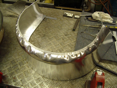
I bought a shrinker when I made my Mk 2 nose cone (don't ask about Mk 1) so I did my inner edge as in post 6 on this thread.
Yes, you need the shrinker to do the outer radiused edge.
It's a case of clamping in the jig and knocking it over till the sheet edge ripples, then use the shrinker to loose some material at the edge.
Repeat this process several times till you get to 90 deg.
Dress out the ripples with a hammer & dolly as much as you can. File and emery paper will take out the rest at the polishing stage.
Cut off the chewed (technical term ) edge that the shrinker has made.
The best piece of advice I've ever been given was from Trev D (aka God).
"Never be afraid of the metal"
I haven't got many pics of the various stages but this pic should scare the sh*t out of you. 
Paul G
Rescued attachment rear-arches-015-s.jpg
|
|
|
907
|
| posted on 9/5/08 at 09:03 AM |
|
|
quote:
Originally posted by TheGecko
quote:
Terrific posts - thanks very much for these details. I've been deliberating about making my own guards and nosecone and this certainly makes
the guards look possible.
On the subject of your curved jig with the pipe: that would be fine if I had easy access to a ring roller (which I don't). Do you have an
opinion about making the front former from hardwood and routing a rounded edge around it?
Also, am I right in assuming that you formed the rounded edges of the guard directly over the pipe former without any use of the shrinker?
Thanks again,
Dominic
Hi Dominic, cheers.
It's all about using the tools that you have, or are prepared to buy.
Your idea of using a hard wood jig is perfect.
Layers of ply, glued & screwed together would work as well.
I did use a shrinker 'cause I've got one.
I also have access to a ring roller at work, and I have an understanding boss.
Paul G
|
|
|
David Jenkins
|
| posted on 9/5/08 at 09:13 AM |
|
|
quote:
Originally posted by 907
... and I have an understanding boss.
That's not what you usually say about him, Paul!
[Edited on 9/5/08 by David Jenkins]
|
|
|
TheGecko
|
| posted on 9/5/08 at 11:27 AM |
|
|
quote:
Originally posted by 907I haven't got many pics of the various stages but this pic should scare the sh*t out of you.
Funnily enough, that pic doesn't actually scare me too much. I've been watching a set of instructional DVD's from these
guys (2 minute Google video preview linky) and they show pretty clearly how
the metal can be made to cooperate. The amazingly cavalier way they start smacking into a flat sheet with a big hammer to start the shaping is quite
a shock They are of the firm belief that you don't need a lot of fancy, expensive tools to achieve good results.
Thanks again for your help. I'm going to hunt around for some dollies and hammers and have a go at some small bits and pieces.
Dominic
|
|
|
907
|
| posted on 9/5/08 at 12:21 PM |
|
|
I can't help noticing that, apart from David who is trying to get me shot,  that all the interest seems to come that all the interest seems to come
from far and wide. Canada, South Africa, Australia...
Where are all the Brits? G/F bodywork must be too cheap here me thinks.
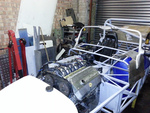
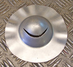
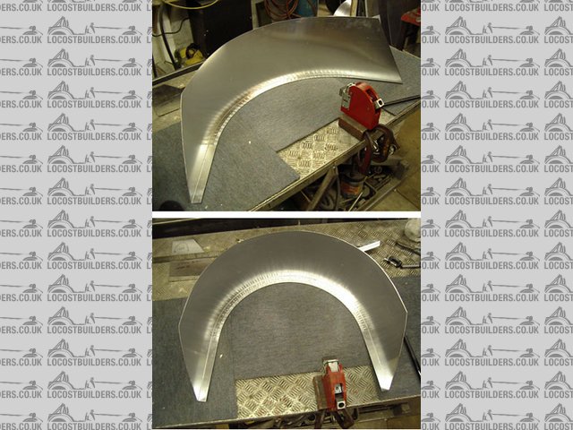
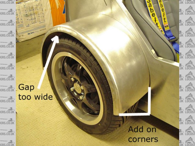
Pic below shows my test one. I added bits on the bottom to blend to the body better, and the gap at the top didn't look right
so I welded in a crescent shaped piece after forming the rad and cutting off the damaged edge the shrinker made.
Paul G
Rescued attachment rear-m-g-4-s-t.jpg
|
|
|