Hornet
|
| posted on 27/2/04 at 03:33 PM |

|
|
Question on tube R
Gents
I was wondering what effect of not bothering to fit Tube R would have? I would prefer not to squeeze it into my engine compartment .. any feedback
would be welcomed.
Cheers 
|
|
|
|
|
GO
|
| posted on 27/2/04 at 04:03 PM |
|
|
Aparently its pretty vital to stop the engine bay twisting.
I wouldn't leave it out!!
Something that has been recommended is a Y tube to give more room in the middle of the bay. What I mean by this is a tube that originates where the R
tube does at the front but comes back straight as opposed to at an angle. Then it joins to the point of a triangle that connects the top of the tunnel
to the corner of the engine bay.
Ideally you'd have a tube either side of the engine.
|
|
|
GO
|
| posted on 27/2/04 at 04:06 PM |
|
|
Nicked from a post by theGecko (cheers gecko!)...
 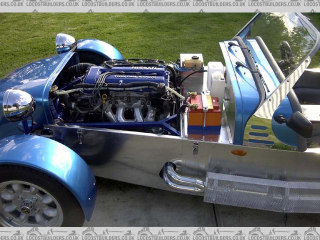
Engine bay of Mike Laws Locost showing modified 'R' tube
link to thread...
Brace bar R
[Edited on 27/2/2004 by GO]
|
|
|
James
|
| posted on 27/2/04 at 06:32 PM |
|
|
Hornet,
A tube here of some sort (standard or 'Y' shape) is vital to the torsional stiffness of the chassis. Better still is if you have 2 of
them! Check the posts by Cymtriks about this.
The only way round fitting these is a whole load of changes to the engine bay side rails and stuff starts getting really heavy! 
HTH,
James
|
|
|
dblissett
|
| posted on 27/2/04 at 09:05 PM |
|
|
another cock up from tiger
thanks lads
i have used the tiger avon chasis as a base for my locost plans and it doesent have a R tube
i will just add this to my list of cock ups from the avon book
cheers dave
|
|
|
scoop
|
| posted on 28/2/04 at 09:16 AM |
|
|
As a worthy point of reference ive been looking at a friends Westfield and they have triangulated the chassis at each corner of the bay with a bar
about 9 inches long. There aint no flex in that chassis!
|
|
|
madforfishing
|
| posted on 28/2/04 at 11:21 AM |
|
|
Has anyone any facts and figures ref. moving Tube 'R' around in the engine bay. (ie. changing the angle / position) ?
Although I only have a little 1600 xflow it is still gonna be a right pain squeezing in twin 40's and the filters.
Has anyone moved Tube 'R' to the other side of the bay ? If so what problems does this bring up ?
If I could keep 'R' on the same side but shorten the length and increase its' angle, that would be fine. I just don't want to
cut it out and re-weld it only to find the chassis' front end is floppy.
I have already added the chassis mods on ronchampion.net so the front is fairly well extra-triangulated, but I appreciate 'R' is a major
factor in stiffening up the whole engine bay 'square'.
Maybe there are some structural engineer guru's with some expensive software out there. Help - I have the grinder ready and I am not afraid to
use it !
|
|
|
dblissett
|
| posted on 28/2/04 at 08:47 PM |
|
|
r brace
i am now thinking of making two hoops to replace the r brace that will go over my twin 40'S on one side and the exhaust manifold on the other
a bit like two strut braces
i know this wont be as strong as a true r brace as the r brace is striaght
but it must be better than none at all
has anyone tried this as its to late for me to change the engine bay
cheers dave blissett
[Edited on 28/2/04 by dblissett]
|
|
|
James
|
| posted on 5/3/04 at 04:44 PM |
|
|
quote:
Originally posted by scoop
As a worthy point of reference ive been looking at a friends Westfield and they have triangulated the chassis at each corner of the bay with a bar
about 9 inches long. There aint no flex in that chassis!
If you mean replacing 'R' with a diagonal just across the corner then apparently it doesn't give much benefit. The only way to
compensate for losing 'R' is a complex sounding system along the sides of the engine bay.
If you search a bunch of Cymtriks' posts then you will see this explained in detail.
HTH,
James
|
|
|
dblissett
|
| posted on 5/3/04 at 06:29 PM |
|
|
r brace
i have 9 inch long braces at each corner this is like the tiger and westfield and i am thinking of puting the hoops in to link these courner braces
together down both sides at least it will give me somewhere to lean on when working on the engine
Cheers dave
|
|
|
craig1410
|
| posted on 6/3/04 at 12:10 AM |
|
|
Hi,
Here is my solution to this problem. I can detect absolutely no flex so far even with the Rover V8 fitted. I tried putting a taught line across the
chassis rails and then jacking up a corner but the line didn't deflect. Not scientific but good enough for me. My mods are not exactly what
cymtriks recommended but include a few ideas of my own along with some of his. Most of it is just common sense to be honest, IMHO of course!
Cheers,
Craig.

|
|
|
Mark Allanson
|
| posted on 6/3/04 at 12:12 PM |
|
|
Craig, It looks really neat and well thought out, an adaption of the idea soon to be appearing on a chassis near me!!!
If you can keep you head, whilst all others around you are losing theirs, you are not fully aware of the situation
|
|
|
craig1410
|
| posted on 6/3/04 at 08:07 PM |
|
|
Why thank you kind Sir! 
As any Locoster knows, there is probably a 3:1 ratio (at least) of thinking to doing so I guess everything is "well thought out"...
To be honest it kinda "evolved" from my initial idea of having the standard SD1 engine mounts bolted to the cradle formed using a couple
of bits of 1" square section. I then found that my triangulation pieces along the side were out of step. By this I mean that the tube (TR1/2)
which normally goes from the bottom corner of the footwell to the top of FU1/2 would now go to the top of the engine cradle tube instead. If I added a
tube from here it would need to go to the bottom of FU1/2 and would foul the suspension bracket. The solution was, as you can see, to add an
extra section of triangulation to coincide with the shortened "R" tubes. A few people have commented the the original design of that book
chassis is badly designed in that TR1 and TR2 are too long and should be made of 1" square section instead of round section. I have used
1" square throughout (2mm thick not 1.6mm) and I think my design will more than make up for the loss of the longer "R" tube.
I'd be very interested in what the FEA programs had to say if anyone fancies knocking it up. Let me know if you need dimensions.
Anyway, thanks again for the positive feedback!
Craig.
|
|
|
cymtriks
|
| posted on 7/3/04 at 02:57 PM |
|
|
tube R
My analysis of engine bay mods (tube R variations)
I have run through some variations on bracing the engine bay. Here are the results for chassis stiffness in ftlbs.
book chassis:- 1155
my modified chassis design as described in earlier posts:- 2505
Both the above have standard tube R layout.
The book chassis with two shorter R tubes, one on each side of the engine, to allow wide engines to be fitted:- 907
My mods but with two short R tubes as above:- 1898
The results show that fitting two short R tubes reduces the stiffness by about 25%
The book chassis but with two Y braces, one on each side of the engine, from where the H tubes meet tube Q to the tops of FU1/2:- 1215
I think that the Y brace idea is the best compromise of triangulating around wide engines or angine accessories.
Also, as in my earlier post on this, the TR1/2 tubes are also highly stressed and really benefit from being 1 inch round 14 gauge or 1 inch square 16
gauge. Replacing TR1/2 with a V, with the point of the V helping to support the engine mounts is a good idea for bigger engines as the G tubes are
getting a bit thin for V8s.
Sorry to be late to post, computer problems are making getting on line tricky.
|
|
|
craig1410
|
| posted on 7/3/04 at 05:05 PM |
|
|
Cymtriks,
Thanks for the refresher on some of your earlier findings.
I looked at fitting Y braces but I just didn't have enough room with the exhaust manifolds and my steering column downlink, hence my alternate
approach. I'm very confident that it will be much stronger than the book chassis.
Cheers,
Craig.
|
|
|
britishtrident
|
| posted on 16/3/04 at 08:36 AM |
|
|
Ok here are the facts:
(1) The diagonal brace R is vital to keep the chassis at something approachining a reasonable torsional stiffness. Ever one for cost saving
Chapman deleted it from the Series 2 Seven but it was put back after owners started experiencing chassis failures.
(2) Two shorter diagonal braces one have been used by some builders such as Westfield to accomodate wide V8 engines -- but short braces across the
corner while a lot better than nothing aren't that good as they put bending loads on the main upper lengine bay tubes.
(3) Caterham when thay actually got round to some chassis development changed to "Y" braces at both sides of the chassis as a result of
computer finite element analysis of the chassis, they also added extra tubes running down from the top front corners of the engine bay to support the
engine mounts.
(4) My own car has member R as per book in addition another diagonal brace will be added to the other side of the engine bay, this will either be
removeable or a short across the corners brace as per the Westie V8 chassis.. Both foot wells and the bulkhead are have additional triangulating
bracing -- the bracing o the drivers side is not diagonal because of the need to accomodate the pedals.
I have also put in extra diagonal bracing to the front frame of the space frame to prevent it lozenging, a well known problem with the original
Lotus chassis.
[Edited on 16/3/04 by britishtrident]
[Edited on 16/3/04 by britishtrident]
|
|
|