j2eDX
|
| posted on 20/3/07 at 06:06 AM |

|
|
Unequal non-parallel suspension, Confused.
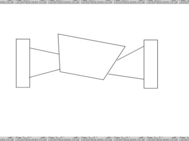
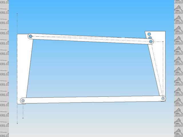
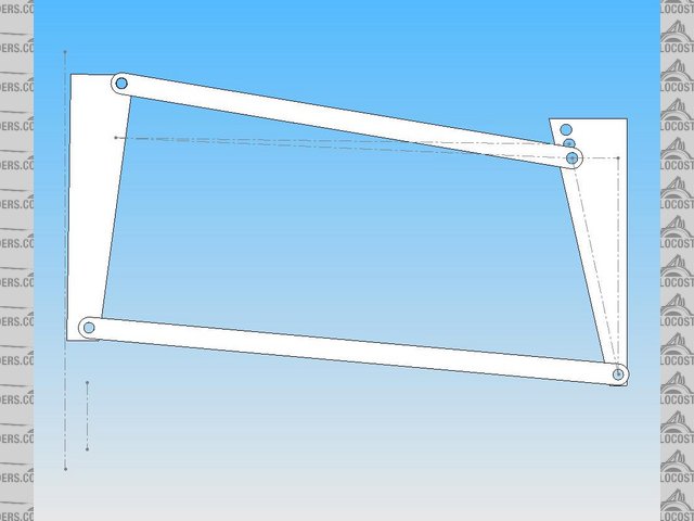
I've been doing research on suspension setup and has done a suspension drawing. From what I read this type of suspension should keep the wheels
perpendicular to the ground when moving up or down. However when I was doing my drawing, I decided to test it out. The upper rod is 12in, 10 degrees
upward from the chassis, and the lower rod is 16in, 0 degrees. To test it out, I drew the top rod 20 degrees down (a mirror image) so there should be
no wheel movement. However if I drew the lower rod 20 degrees down, the lower wheel moved inward. So to my understanding the un-parallel doesn't
allow the wheel to remain perpendicular to the ground during movement, and the parallel setup does. If anyone could explain to me how it works,
thanks.
 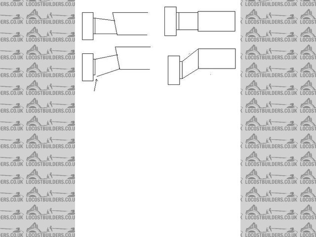
Rescued attachment non-parallel vs parallel.JPG
|
|
|
|
|
nitram38
|
| posted on 20/3/07 at 06:39 AM |
|
|
The idea of unequal wishbones is that when cornering, your car body roll will allow the wheel tread to stay in contact with the road.
Your wheel camber settings will change with body roll.
If they didn't change, then the tyres would lose grip.
In an equal parallel setup, your wheels would remain parallel to your body roll, so lifting part of the tread patch from the road.
With an unequal setup if your wheel goes upwards then you should increase negative camber and downwards, become more positive.
Do a search for some of my posts and you will be able to find some diagrams of my next project setup.
|
|
|
Mal
|
| posted on 20/3/07 at 07:46 AM |
|
|
Suspension geometry
For most amateur builders the distance between the pivot centres on the suspension uprights are fixed, because an uprights from a production vehicle
is being used, eg the Cortina.
However, this still leaves plenty of combinations and permutations of relative upper to lower wishbone length and chassis pick up points. It is not
easy and you will need to do many plots of roll centre for various amounts of wheel travel.
Begin with the track width you want, draw the positions of the pivot centres on the uprights. Draw the initial postions of the chassis members that
will take the inboard brackets. Link the inboard and outboard pivot points with the right sort of wishbone length and inclination in the static
position. Plot the roll centres for different amounts of suspension travel.
Adjust wishbone lengths and pivot positions and plot until you get the desired result or you are overcome by insanity, whichever arrives sooner.
Good luck.
|
|
|
Peteff
|
| posted on 20/3/07 at 11:57 AM |
|
|
You have to picture the body roll to see what you want to achieve. As the body rolls it pulls and pushes the wishbones altering the wheel camber, your
picture doesn't show that it assumes that the wheels and body stay in the same relative positions under different circumstances. You need to look
at some action photos, the body doesn't stay horizontal like your diagram and pushing and pulling forces are in effect.
[Edited on 20/3/07 by Peteff]
Rescued attachment bodyroll.jpg
yours, Pete
I went into the RSPCA office the other day. It was so small you could hardly swing a cat in there.
|
|
|
t.j.
|
| posted on 20/3/07 at 08:16 PM |
|
|

We all had the same thoughts
As the car "rolls" at cornering you want the wheel fixed to the ground. So normally your outher wheel must be corrected by some negative
camber.
If you have a formula 1 (stiffer) there will be less roll so equal wishbones is not the problem there.
I calculated etc. etc.
In my opinion from important to less important:
- Bumpsteer
- Caster.
- Camber.
- Toe in/out
- Tyre presure
- roll-centre (static)
- camberchange due cornering
- rollcentre (change)
Grtz Theo
Advise: Read read read , and then just admire the non-logic construction on much sevens :-)
And then make the best you can your self. Drawing exactly is one, making is two
|
|
|
907
|
| posted on 20/3/07 at 08:46 PM |
|
|
Build a moving model of your suspension with lollipop sticks.
It may not be the best way to understand suspension...
but the lollipops are nice.

Paul G
|
|
|
nitram38
|
| posted on 20/3/07 at 08:54 PM |
|
|
From a book:
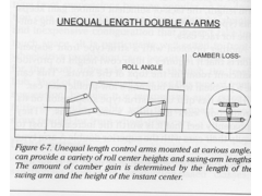 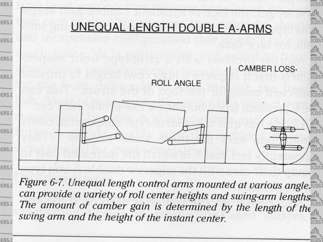
unequal wishbones
From my modelling in solidworks you can see the camber changes for my next car:
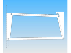 
Description
up
[img][/img]
|
|
|
j2eDX
|
| posted on 21/3/07 at 08:36 AM |
|
|
Thanks for the information guys. From what I read on double a-arms. The arms should be unequal and non-parallel. What parts do they mean by unequal,
non-parallel. Does it mean unequal lengths of upper vs lower arm or lengths of the arms forming the wishbones. When it says non-parallel, does it
refer to the upper to lower arm or angle of A-arm (if it was parallel then it wouldn't be A-arm anymore) What is a good angle for the unequal
arms and angles of the upper & lower arms. I read that the lower arm should be longer than the uppe. The lower arm should be horizontal and upper
arm tilting upward from frame. I also have a hard time deciding the distance between the upper and lower arm at the frame. Should the distance
between the upper and lower arms the same as the arms at the hub (then it wouldn't be non-parallel anymore right)? At riding height, how should
the arms look like for best camber control? The lower arm horizontal and upper angled up or both angled upward. Sorry for so many questions, I am
still waiting for my library book holds to arrive so I don't have much base knowledge. I really appreciate you guys' help.
[Edited on 21/3/07 by j2eDX]
[Edited on 21/3/07 by j2eDX]
[Edited on 21/3/07 by j2eDX]
|
|
|
MikeRJ
|
| posted on 21/3/07 at 09:52 AM |
|
|
Unequal simply means unequal length, the upper is usually shorter than the lower (hence the shape of the front of the locost chassis).
Non-parallel means just that, the upper and lower arms in most roadgoing double wishbone designs are not parallel, typically they will be converging
towards the chassis.
Have a look at http://www.ukcar.com/features/tech/suspension/wishbone.htm for some pictures.
No one can tell you what some good numbers are for your suspension, it totally depends on design of your chassis, what uprights you are using etc.
Designing optimal suspension geometry is not a trivial exercise, hence the number of books written on the subject.
|
|
|
t.j.
|
| posted on 21/3/07 at 05:38 PM |
|
|
The scrubbing effect as discribed by equal lenght is always there.
Don't think it will work in home design, to prevent this!
Stay with the static rollcentre idea, design with as less bump-steer as possible. And you will be fine.
Let the lower and upper brackets parrallel.
The anti-dive or dive isn't the problem.
My upper and lower wishbone are parrallel but both under 5,5 degr attached (so rear bracket lower then the front, but parrallel to the upper
brackets!)
The most scrubbing will be "picked up" into a good tire. So tyre presure and wheel allighment are important.
[Edited on 21/3/07 by t.j.]
|
|
|
nitram38
|
| posted on 21/3/07 at 05:42 PM |
|
|
I though scrub was caused by kpi (king pin inclination) on the front wheels.
What scrub are you talking about?
|
|
|
t.j.
|
| posted on 22/3/07 at 07:09 PM |
|
|
"Traditional double wishbones consists of 2 parellel wishbone arms of equal length, which has the drawback of excessive tire scrubbing because
of the large variation in track width as the wheel moves off the neutral position."

|
|
|
j2eDX
|
| posted on 23/3/07 at 04:18 AM |
|
|
I'm wondering if someone could provide me with a suspension blueprint to look at. A picture is worth a thousand words. It would be a great help
to me and others.
|
|
|