Miks15
|
| posted on 11/2/08 at 09:38 PM |

|
|
new chassis design
Just after some of your opinions realli
I did buy a locost chassis from someone but now ive had time to look a bit closer, its..well...rubbish
Not at all straight and all the welds look dodgy
Plus it didnt look like my engine was going to fit
so i decided just to make my own around my engine and have it slightly wider aswell.
So what do you think?
Image deleted by owner
Bearing in mind also there will be some round bar triangulation like on the book chassis and i couldnt be bothered to finish the trans tunnel which is
why theres still a gap there
So opinions please, any possible problems in the design anyone can see?
thanks guys
|
|
|
|
|
iank
|
| posted on 11/2/08 at 10:16 PM |
|
|
OK, firstly you need triangles everywhere not rectangles.
IMO the best way to get a feel for chassis design is to buy a big pile of balsa wood strips from a craft/model shop. Something around 1/16"
square section is good. Then build your chassis to scale (1:16  ) using a glue gun (be careful it's hot). Then get hold of it and twist the
model around the suspension pickup points. You'll soon see what makes a stiff chassis and what makes a floppy weak one. ) using a glue gun (be careful it's hot). Then get hold of it and twist the
model around the suspension pickup points. You'll soon see what makes a stiff chassis and what makes a floppy weak one.
--
Never argue with an idiot. They drag you down to their level, then beat you with experience.
Anonymous
|
|
|
minitici
|
| posted on 11/2/08 at 10:23 PM |
|
|
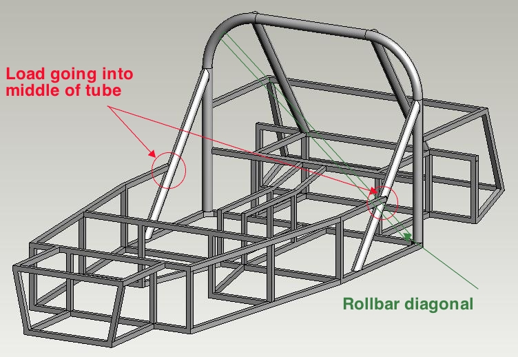
As above and don't put loads in the middle of tubes.
|
|
|
james h
|
| posted on 12/2/08 at 12:32 AM |
|
|
Was this drawn in solidworks? If so you can run this progamme in it (COSMOSXpress) to show the stresses in the chassis and any twisting you might
encounter when differing loads are applied at any point.
I think what you will find is that your design will need to be reinforced as ian and minitici say.
|
|
|
Maradona
|
| posted on 12/2/08 at 12:38 AM |
|
|
keep im mind, triangles, that is the most powerful estructure. You can experiment doing your design in scale in wood, that is the best way.
cheers
Diego,
The locost builder from Argentina
|
|
|
Alan B
|
| posted on 12/2/08 at 12:50 AM |
|
|
quote:
Originally posted by james h
Was this drawn in solidworks? If so you can run this progamme in it (COSMOSXpress) to show the stresses in the chassis and any twisting you might
encounter when differing loads are applied at any point.......
How?.....I've never had any luck beyond a simple bracket..is it done as a part?..weldment?..assembly?....any good hints would be helpful..
Cheers,
Alan
|
|
|
Mr Whippy
|
| posted on 12/2/08 at 08:54 AM |
|
|
Make a balsa wood model, 1 foot long, using 5mm square sticks & white glue. You will then soon seen how it performs. Once happy with it, sheet
with thin card for the panels. All these 3D stress tools are fine but still can't beat a hands on model IMP.
Fame is when your old car is plastered all over the internet
|
|
|
Miks15
|
| posted on 12/2/08 at 09:47 AM |
|
|
cheers fo all the replys guys will go down for some balsa wood later
How can i overcoome the problem of the load in the middle of the tube?
|
|
|
MikeRJ
|
| posted on 12/2/08 at 10:05 AM |
|
|
quote:
Originally posted by Miks15
cheers fo all the replys guys will go down for some balsa wood later
How can i overcoome the problem of the load in the middle of the tube?
Triangulation is your friend!
Description
|
|
|
iank
|
| posted on 12/2/08 at 10:15 AM |
|
|
quote:
Originally posted by Miks15
cheers fo all the replys guys will go down for some balsa wood later
How can i overcoome the problem of the load in the middle of the tube?
You can support it by adding another tube by from the red circle to the base of the roll hoop. making the big triangle into two smaller ones.
It is important to realise all spaceframes are a compromise and will have non-ideal forms else you'd never be able to fit engines and
people in them.
Have a read of cymtrix's paper, there's lots of good design hints in it.
http://www.locost7.info/mirror/chassis.php
kitcaranalysis_V2.doc.
Also
Final Thesis B.doc
Aussie Mods
Another way to approach it is to design the suspension first, then put engines/people/fuel tanks in place. Finally create the chassis around that
lot (probably iteratively changing things as you go).
--
Never argue with an idiot. They drag you down to their level, then beat you with experience.
Anonymous
|
|
|
02GF74
|
| posted on 12/2/08 at 10:15 AM |
|
|
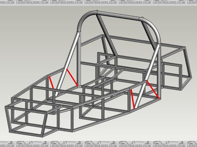
load not in middle of tubes - so what about these other tube that have a tube butting in the side, some are highlighted?
does t he principle nbot apply t ot them, and if not, why not?
|
|
|
Miks15
|
| posted on 12/2/08 at 12:26 PM |
|
|
quote:
Another way to approach it is to design the suspension first, then put engines/people/fuel tanks in place. Finally create the chassis around that lot
(probably iteratively changing things as you go).
That is what ive tryed to do,
Ive tryed to use the same dimensions for the front suspension as the orignal book chassis, but then make the main shape slightly wider for bigger
seats, and also for my engine (looked very tight in a standard chassis.
But then the rear end was trickiest and im sure it will need more strengthning but i will look at that later on.
Any other insights will be greatly appreciated
Thanks for all responses so far guys
|
|
|
MikeRJ
|
| posted on 12/2/08 at 04:40 PM |
|
|
quote:
Originally posted by 02GF74
load not in middle of tubes - so what about these other tube that have a tube butting in the side, some are highlighted?
does t he principle nbot apply t ot them, and if not, why not?
He did mention in the first post that he hasn't put the normal triangulation in the model yet.
|
|
|
Miks15
|
| posted on 12/2/08 at 09:53 PM |
|
|
apart from some more triangulation needed,
is there anything else anyone can point out?
would be much appreciated
|
|
|
Schrodinger
|
| posted on 13/2/08 at 12:45 AM |
|
|
The transmission tunnel just ends but should continue forward, probably just missed out.
Keith
Aviemore
|
|
|
Miks15
|
| posted on 13/2/08 at 09:58 AM |
|
|
haha ye i realised that, i just couldnt be bothered to finish it off since its off in two different angles, takes a little time too do and wasnt in
the mood after doing the whole chassis, ill probs do it later.
|
|
|
britishtrident
|
| posted on 15/2/08 at 12:10 PM |
|
|
Triangulation isn't something you add in it is the core of what makes a framed structure stiif.
Imagine each joint between tubes as a pinned joined -- ie the welds don't have any ressistance to bending. None of the tubes should be loaded in
bending only in tension or compression -- although this is more a goal than something that can be 100% achieved.
If you really need a longer wider taller chassis start with the 4-4-2 and modify it.
[Edited on 15/2/08 by britishtrident]
|
|
|
britishtrident
|
| posted on 15/2/08 at 12:11 PM |
|
|
quote:
Originally posted by iank
OK, firstly you need triangles everywhere not rectangles.
IMO the best way to get a feel for chassis design is to buy a big pile of balsa wood strips from a craft/model shop. Something around 1/16"
square section is good. Then build your chassis to scale (1:16 ) using a glue gun (be careful it's hot). Then get hold of it and twist the
model around the suspension pickup points. You'll soon see what makes a stiff chassis and what makes a floppy weak one.
Good advice and loads of fun !
[I] What use our work, Bennet, if we cannot care for those we love? .
― From BBC TV/Amazon's Ripper Street.
[/I]
|
|
|