xico_ze54
|
| posted on 21/3/07 at 04:43 PM |

|
|
Propshaft alignment
Hi,
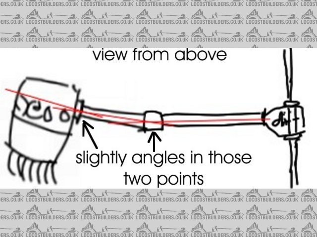
please see this pic attached and tell me if we can put a bike engine maximum far right, to use in a LHD car, and put some angle in those U-joints?
is there some danger in broke propshafts or U-joints at high rpm?
thks
Amadeu
Rescued attachment new-2.jpg
|
|
|
|
|
BenB
|
| posted on 21/3/07 at 04:45 PM |
|
|
IIRC props work best with a slight angle on the joints and cant go wrong if you run it absolutely straight. Not sure where I remember that from!!!!
|
|
|
Hellfire
|
| posted on 21/3/07 at 04:49 PM |
|
|
A UJ is designed to run with an angle so no fear of problems here. They are made to run with a (IIRC) 5 degree minimum.
Your engine has no effect on the speed of rotation of the propshaft, it's dictated by the speed of the wheel/differential ratio. You won't
break a properly designed propshaft on a slightly modified seven (read - PROPERLY). The se7en weight is almost half it was originally designed for.
Steve
|
|
|
worX
|
| posted on 21/3/07 at 04:50 PM |
|
|
I'm not sure about having the angle between the engine/prop adaptor to the prop - I would of thought that it would be a lot better if those
mating faces were at 90degrees to each other?
I am only going from what I think, not from proven fact so maybe someone else on here can confirm/deny.
the mid bend in the prop is more than fine, it can be angled a lot further than that, as mine is already!
hth
cheers,
Steve.
[Edited on 21/3/07 by worX]

|
|
|
Bluemoon
|
| posted on 21/3/07 at 05:18 PM |
|
|
Allways wondered how the BEC get way with it. The yokes should be phased at 90 degrees (in theory) and outputs shafts at each end should be in parall,
but offset to allow the UJ's to work otherwise you wear flats in the bearings..
Would like to hear what others think about this..
Cheers
Dan
[Edited on 21/3/07 by Bluemoon]
|
|
|
jcduroc
|
| posted on 21/3/07 at 05:30 PM |
|
|
quote:
Originally posted by xico_ze54
Hi,
please see this pic attached and tell me if we can put a bike engine maximum far right, to use in a LHD car, and put some angle in those U-joints?
is there some danger in broke propshafts or U-joints at high rpm?
thks
Amadeu
Amadeu
I would place the engine on the RHS and make a reverse box from the pinion to the CL of the car.
JCM
|
|
|
02GF74
|
| posted on 21/3/07 at 05:32 PM |
|
|
hmmm .... I always thought the important bit was to have the drive flange (on engine) parallel to the driven flange (axle) and the angle does not
matter too much providing it is not more than the UJ can take.
if you angled your engine so the drive flange was in vertical plane, then I would have no problems but like you have it, not sure.
read all about propshaft angles here
|
|
|
Bluemoon
|
| posted on 21/3/07 at 05:55 PM |
|
|
02GF74, yep that's what I was trying to get at...
Dan
|
|
|
xico_ze54
|
| posted on 21/3/07 at 06:13 PM |
|
|
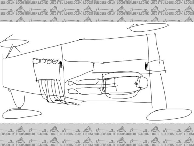
so... what´s the best solution?
so... what´s the best solution? bearing in mind the driver will sit on left and the problems of much weight on left side. plus the steering column
have to have room to pass though, gives no other chance than put that engine some distance to the right side.
can anyone sketch over my sketch an ideal solution to this problem?
Rescued attachment new-3.jpg
|
|
|
Peteff
|
| posted on 21/3/07 at 06:14 PM |
|
|
You'll need a sliding joint in the front section where it connects to the engine or it will shake the joint to bits. Prop suppliers have these.
yours, Pete
I went into the RSPCA office the other day. It was so small you could hardly swing a cat in there.
|
|
|
ChrisGamlin
|
| posted on 21/3/07 at 06:29 PM |
|
|
As others have said, the two flanges should ideally be parallel, and as I mentioned in another thread recently, don't forget to consider
VERTICAL angles as well as the horizontal ones you're looking at here, i.e. if the output shaft is vertically higher / lower than the diff
flange, you have an angle there as well.
Im not sure about it shaking the joint to bits without a slider though Pete, all live axle BECs have to have the slider in the rear half for obvious
reasons and Ive never heard of any trouble at all with the front UJ.
In fact, I would actually suggest the slider on the rear with a fixed length at the engine end, because if your prop flange on the engine ever comes
loose (and they do - mine did), with a slider on the front the prop is able to disengage from the engine and potentially cause serious injury, with
the slider on the rear half it will simply cause some extra vibration but won't be able to escape off the output splines.
cheers
Chris
[Edited on 21/3/07 by ChrisGamlin]
|
|
|
xico_ze54
|
| posted on 21/3/07 at 07:03 PM |
|
|
Chris,
just finished to see one of the pics you show in your archive (named: R1 Prop angle) and it's like I have talked first.
in that photo your sprocket isn't in the centerline of the car, making an some angle with the first shaft, the same with centre bearing.
do you want to coment that?
|
|
|
JoelP
|
| posted on 21/3/07 at 07:27 PM |
|
|
the two prop mating faces need to be parallel because a u/j isnt a constant velocity joint, if they arent square you get a pulsing of motion rather
than constant at both ends. The worse the angle the more the drivetrain gets abused. I have no idea how badly this will affect it, but thats the
theory. However, the engine can happily be off the centreline.
If i was building a LHD bec, i would leave the feet areas out until the engine was being positioned, and balance them around each other. You can take
a chunk out of the passanger (right hand side) footwell to allow the engine further over.
|
|
|
ChrisGamlin
|
| posted on 21/3/07 at 08:24 PM |
|
|
quote:
Originally posted by xico_ze54
Chris,
just finished to see one of the pics you show in your archive (named: R1 Prop angle) and it's like I have talked first.
in that photo your sprocket isn't in the centerline of the car, making an some angle with the first shaft, the same with centre bearing.
do you want to coment that?
Hi Amadeu
I assume you mean this one, which Ive modified to show the differences...
 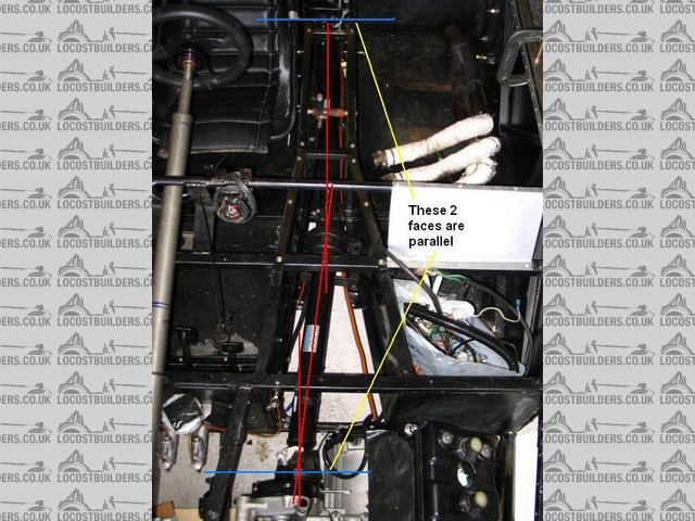
Prop Angles
As you can see, my prop angles are different to your picture because my engine is mounted inline with the chassis centreline, not at an angle across
the chassis like in your drawing. This means my output and diff flanges (blue lines) are parallel with each other and the angles of the prop cancel
themselves out along its length.
cheers
Chris
[Edited on 21/3/07 by ChrisGamlin]
|
|
|
xico_ze54
|
| posted on 22/3/07 at 10:52 AM |
|
|
Chris,
thanks for the modified pic to observe the explanation.
so the 'receipt' to a good job is to put diff & sprocket flanges paralel. I see.
|
|
|
matt_gsxr
|
| posted on 22/3/07 at 11:59 AM |
|
|
3 simple options:
1) find an engine which has the prop coming out of the other end. That is a bike with a sprocket on the left.
2) move to England and build it RHD.
3) chop your legs off.
No no no, there is no need to thank me.
Matt
|
|
|
grb
|
| posted on 22/3/07 at 12:04 PM |
|
|
quote:
Originally posted by matt_gsxr
1) find an engine which has the prop coming out of the other end. That is a bike with a sprocket on the left.
my KTM LC4 is... (and would be rubbish in a car!) ...but I wonder if the LC8 V-twin is too?
grb.
|
|
|
robertwa
|
| posted on 22/3/07 at 03:32 PM |
|
|
Take a look at this LHD BEC to see what he has done:
Left hand drive R1 BEC
|
|
|
Peteff
|
| posted on 22/3/07 at 04:26 PM |
|
|
all live axle BECs have to have the slider in the rear half
I don't think the Isonblade has, I'm sure his is in the front. The centre bearing mount has enough flex to cover live axle movement, same
setup,Transits, Marinas and plastic pigs with 2 piece prop didn't have a sliding joint in the rear only the slider at the gearbox end.
if your prop flange on the engine ever comes loose (and they do - mine did)
Ever thought why this happened?
[Edited on 22/3/07 by Peteff]
yours, Pete
I went into the RSPCA office the other day. It was so small you could hardly swing a cat in there.
|
|
|
ChrisGamlin
|
| posted on 22/3/07 at 09:28 PM |
|
|
Hi Pete
I guess there probably would be enough flex in the centre bearing to cope with a live axle moving at the rear, but if thats the case there's
certainly enough to accomodate any movement on the engine end.
FWIW my bolt loosened itself a bit despite being correctly torqued / threadlocked. I caught it in time after I noticed the vibration, but the flange
couldnt come off anyway because of the fixed prop length, had it been a slider its possible it could have sheared the bolt head off even if it hadnt
come fully undone, which is what appeared to happen to a car on the Yahoo list a while back (I forget who).
Hopefully not such a problem on the R1 though as they have tabbed washers to hold the nut as well as copious amounts of threadlock, but I can't
see a lot of point in tempting fate by putting the slider at the front if you have the choice.
cheers
Chris
|
|
|
Peteff
|
| posted on 23/3/07 at 12:11 AM |
|
|
, had it been a slider its possible it could have sheared the bolt head off even if it hadnt come fully undone
If it had been a slider it wouldn't have happened. A slider would be engaged by at least 50mm so if it disengages your engine has fallen out.
Guess all you like about the centre bearing, Ford have been doing it like that for years and they don't guess. 
yours, Pete
I went into the RSPCA office the other day. It was so small you could hardly swing a cat in there.
|
|
|
ChrisGamlin
|
| posted on 23/3/07 at 08:37 PM |
|
|
Pete, I used the word "guess" as a figure of speech which I'm sure most people picked up on without too much bother, I could have
just as easily used "can see", or "accept". You obviously failed to recognise that though judging by the slightly patronising
tone to your reply.
quote:
If it had been a slider it wouldn't have happened.
Errr, prop sliders have bolt tightening tendancies ?
quote:
A slider would be engaged by at least 50mm so if it disengages your engine has fallen out.
You've clearly got the wrong end of the stick Pete! Im not talking about the slider itself extending to the point that it disengages from the
rest of the prop, Im talking about the slider allowing the prop to shorten and so allow the prop flange to drop off the output shaft. Some output
shafts are only ~15-20mm deep, so you only need that amount of travel in the slider for the flange to disengage.
[Edited on 23/3/07 by ChrisGamlin]
|
|
|
Peteff
|
| posted on 23/3/07 at 11:40 PM |
|
|
judging by the slightly patronising tone
No that was sarcasm Chris, I knew it wouldn't be long before you replied.
My point was that if there'd been a slider on there would have been no stress on the nut and it wouldn't have come loose in the first
place.
Your go, I've done now.
yours, Pete
I went into the RSPCA office the other day. It was so small you could hardly swing a cat in there.
|
|
|
ChrisGamlin
|
| posted on 25/3/07 at 08:22 PM |
|
|
Pete
You're still making statements as fact without actually saying why, if you're going to argue against it then why not explain why you
believe a fixed length prop puts stress on the engine UJ / flange?
As you've said yourself, the centre bearing has enough movement in it to allow a live axle to move at the rear, so how does this suddenly become
non applicable when discussing the comparatively fixed span of engine to centre bearing?
If your engine is moving fore/aft more than your live axle, you have some serious problems that a prop slider isn't going to fix! 
Chris
BTW, I really don't want to turn this into a slanging match but you're seemingly writing in a condescending manner without realising!
Sarcasm by definition has an element of humour / wittyness / irony about it, saying "Guess all you like..." in reply to something I said
is a plain attempt at a put down, suggesting you believe you're knowledge is superior. This makes the comment patronising, not sarcastic.
[Edited on 25/3/07 by ChrisGamlin]
|
|
|
Peteff
|
| posted on 26/3/07 at 04:24 PM |
|
|
Look at his diagram Chris.
Unlike your prop, the angles on his will not cancel each other out. The rear is straight and the front is angled so the prop will pulse or phase as
the prop turns as Joel said. As it is the front which is at an angle and the rear is straight he will need the slider in the front as I will with mine
and Jon does in his. I have consulted with a manufacturer and his suggestion was a slider in the front and a torque tube in the rear for my
application which is like xico's but angled to the other side. As he says, the ideal would be to mount the engine with the joints parallel but
it's not always practical.
I'm sorry that I couldn't let it go but why should I not take my position in this and only see yours, you mentioned my name in your post
prompting me to retaliate Chris. Why is it only condescending or patronising when I say it?
Im not sure about it shaking the joint to bits without a slider though Pete, all live axle BECs have to have the slider in the rear half for
obvious reasons and Ive never heard of any trouble at all with the front UJ.
Does this sound a touch condescending as well, it does to me. I can't see the reason for a slider in the rear however obvious it is to you and
you have made no effort to explain to me just told me I am wrong and put me in a negative frame of mind. I would not resort to name calling and
insults on a forum any more than anywhere else,
"In fact, I would actually suggest the slider on the rear" sounded to me that you were calling my suggestion wrong implying that I
do not know what I am talking about and causing me to take umbrage.
[Edited on 26/3/07 by Peteff]
yours, Pete
I went into the RSPCA office the other day. It was so small you could hardly swing a cat in there.
|
|
|