

http://photos-f.ak.fbcdn.net/photos-ak-snc1/v375/98/84/647682560/n647682560_1040373_9595.jpg

heres some updates of my project
http://photos-f.ak.fbcdn.net/photos-ak-snc1/v375/98/84/647682560/n647682560_1040373_9595.jpg
that looks lots of fun cool
Very nice
that looks GREAT!!! What a well proportioned effort. It looks like you have a very long wheelbase. Mind if I as what it is?
Your photos are wonderful btw. Very whimsical of you to take them like that. I really like the look of 'effort' on both of your faces. It
made me smile.
thanks for the compliments. it took ages to design and get the proportions right.
I took the photos with my cellphone, and thats not me, its my brother and cuz, they offerd to be my show girlz
the wheelbase is 2750mm
Also, love the rims. What are they?
quote:
Originally posted by chris mason
what engine are you using?
ah! subaru engine
Chris
what sort of subaru engine? thats doesnt look flat 4?
Speedy progress - It looks awesome!
its a vw 1600 transverse mounted engine with a 2ltr 16v gbox, AYH/02A gbox with a cable shifter selector. Not that powerful but counting on the weight
to make up for that. Wud hav loved a flat 4 subaru engine, but it would have taken up too much space.
Wheels are lightweight Envy mags, i think made locally here in South Africa.
Front hubs are from a cortina, rear are vw. made my own floor mounted pedal box as well.
Seats are lightweight STS, i think its italian seats.
Sgraber and Warner, ur cars rock!Sgraber, i love ur engine bay, looks very professional. It had to b kinda speedy coz i did it for my Btech industrial
design project.
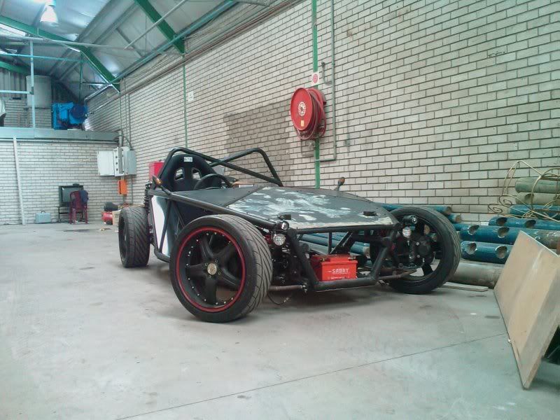
busy making the body panels, will update tomorrow
[Edited on 15/11/08 by Gakes]
This is how the radiator would sit in a mk1 Golf:
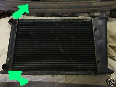
Will it be a problem if I mount it vertical, like this?
A mechanic told me that the cooling fluids wont flow properly through the radiator, instead, the fluids will take a shortcut and just flow across the
top tank.
Wot do u guys think?
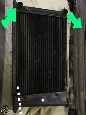
Fluids always take the easiest route. Put a new exit at the bottom of the radiator, diagonally opposite to the top inlet.
So I just block off the bottom outlet and make another one in the bottom opposite corner. the tanks are plastic, how do i make another outlet??
Check your rad - some have an internal partition at the hose end to force water to take the path to the bottom cap
James
Yeah it must have an internal baffel between the inlet and outlet. Stick a piece of wire in there and see, or use a dentist mirror. No way it's a straight shot across.
so then it might work???thats the next question I wanted to ask.
I will check it tomorrow
Agreed, it's likely to be a double pass style...bit like this...
linky
makes sense, it would b pointless any other way
With all that room in the front, you could almost make it a front engine configuration! Excellent work and great to see you behind the wheel making
BRRRM BRRRM noises.
P.S You've gone one better than BRRM BRRM with it on a trailer actually 
Thats my baby brother in the drivers seat, he's my BRRRMMMM BrrM sound engineer
Evertyhing is almost done except for any body panels, Im waiting on a friend to get me some carbon for low price.
Will be starting up this evening hopefully coz we finishing up the wiring.
Does anyone have internal pics of a fueltank coz I'll be making mine soon.
I have mounted my coolant rervior lower then the top radiator tank. I 'm hoping it will work bcos there is a waterpump that circulates the
fluid.Does anyone know if this might work:

Is it possible to remove the brake booster from the brake master cylinder? Will it make a major difference in the brake efficiency?

Hi Gakes
quote:
I have mounted my coolant rervior lower then the top radiator tank. I 'm hoping it will work bcos there is a waterpump that circulates the fluid.Does anyone know if this might work:
On the couple of cars I've managed to get info on, the vac assist gives a 1.8 to 2 times gain. E.g, without the servo you will have to press the
brake pedal twice as hard for the same braking effect.
Regards
Hugh
oK, so ill just add another master cylinder to increase hydraulic force.
Fred, I just put a steel plate under the ally to stabilize it a bit more.
quote:
Originally posted by Gakes
oK, so ill just add another master cylinder to increase hydraulic force.
Makes sense. The only problems I had with the booster was its shear size and connecting it to the intake bcoz now I'm running a dowdraught.
No problem, look around in wreckers for isolated brake boosters or speak to your local brake parts shop, they aren't always located just in front
of the mastercylinder.
You really need to top your water at the highest point and have bleeds anywhere that large amounts of air can get trapped and I see you have this
problem.
[Edited on 21/1/09 by cheapracer]
I've never seen any of those before,thanx for the advice. I've found a better place to mount the bottle. seems like it will work out.
Had my first test drive in the xO!!!!!!!!!!!!!!!!!!!
Went ok, still a couple of snaggs.
http://www.facebook.com/video/video.php?v=62435622560&oid=14494654031
Does anyone know why my car's not getting enough grip on the front wheels when i turn??
Toe in/ Ackerman change problems at a first guess...
James
was thinking it might be that, do u perhaps think I need more weight on the front?I've never weighed it yet
I don't think it's that - mine's fine and it's only about 55kg on each wheel....
Any suspension guru's about?
James
Have you checked rear diff? on the video it seems that front is pushed straight by 100% closed differential. Just lift one rear wheel and try to
rotate it.
Just a guess as I'm not susp guru anyway.
----------
BTW First post so... hi everybody, I hope to finish planning some day
good call - it's possible
Although vids can be decieving, from looking at your video frozen at 0.52 seconds and the push, I would suggest you have reverse ackerman steering.
Post a few pics of the front end for me with the wheels off (plan view would be good directly above 1 of the uprights) and we'll have a look.
quote:
Will it be a problem if I mount it vertical, like this?
A mechanic told me that the cooling fluids wont flow properly through the radiator, instead, the fluids will take a shortcut and just flow across the top tank.
Wot do u guys think?
I think i found the problem, instead of having reverse ackerman, I have too much of an ackerman angle probably. I should be within 4 to 6 degrees of
steering axis but I'm rolling on about 11degrees (looking from the side profile). I measured out all the angles and found out that when I changed
my suspension design from bushes to rod-ends, I miscalculated the hinge centres and now I'm out by a couple of mm's.
Its not too much of a loss as i want to extend my track by 40-50mm on each end
Nah, maybe it's an optical illusion but I swear at 51 and 52 seconds your inside tyre isn't turning anywhere near as much as the outside is and that would explain your phenomenemenenen (can anyone actually spell that?).
..and middy locost builders please note, the VDub motor (Golf, Jetta) has the inlet manifold to the front and exhaust to the rear - handy arrangement.
Thats for 16valve VW engines, 8valve VW engines have the inlet and outlet at the rear, but the inlet sits above the exhaust outlet. For this reason,
water is channeled from the radiator/heater pipes into the inlet to cool it down,bcoz its above the exhaust outlet.....just by the way
quote:
Originally posted by Gakes
Thats for 16valve VW engines, 8valve VW engines have the inlet and outlet at the rear, but the inlet sits above the exhaust outlet. For this reason, water is channeled from the radiator/heater pipes into the inlet to cool it down,bcoz its above the exhaust outlet.....just by the way
Hi all,
Did some revision changes to my plans to make the build easier and cheaper.
So now I'm selling them at 350U$ dollars if anynone is interested. Visit
http://sites.google.com/site/xocars/ for info or ccontact me xosportscars@gmail.com
Follow threadForum thread
[Edited on 6/3/09 by Gakes]
I think the wheelbase is 25 to 30 cm too long.
Hi Designer. Why would you say that??
I had to remove my cylinder head, I bypass the heater pipe section and the water pipe to cool the intake loaded the the engine with water, bugger.
Then when I repaired every thing, I cracked the cam holder mounts in the head. Been a rough few weeks but bought a new head for about 20 Pounds and
fitted a 268 degree cam and a Weber downdraught. will be starting up tomorrow morning.
And I widened the front track, and busy with the new rear suspension and pedal box.
[Edited on 1/4/09 by Gakes]
Hi
If you look at the lower picture (side view) of your initial post, there would seem to be a long way from the soles of the drivers feet to the front
suspension.
Probably, floor mounted pedals will be used and I would seem that it will be difficult to solidly mount them without having a very solid, thicker than
necessay, floor, whereas pedal sets are usually braced to a bulkhead.
This is only my opinion of course.
Otherwise, you are doing a good job.
I was concerned that there was going to be too little space for extra bits I wanted to add and maybe wanted to mount a fuel cell in front.
I made my center console today, will fit it in tomorrow.
Great to see your still into it Gakes, good luck hope you take some of the local hints for what it is - constructive hints!
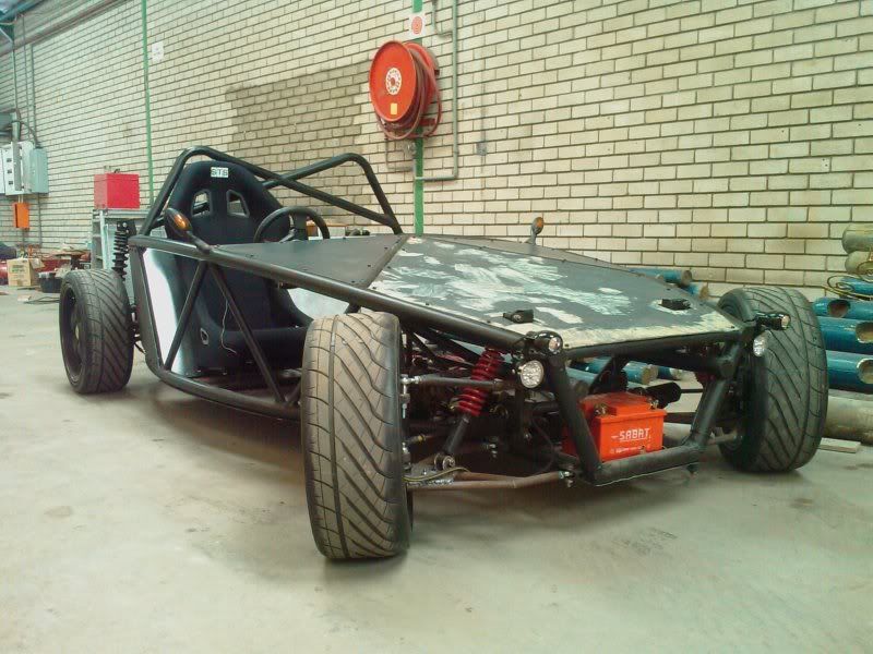
For sure.Heres some update pics, new front suspension and tunnel in. The car sits much better and turns well:
Ok, the shape/style your trying to get to is becoming clearer and more interesing.
Mate a little more constuctive hinting.
Your lower control Aarms, I see no reason at all why they aren't simple triangles? I see the top Aarm you are trying to clear the shocker, fair
enough and there is lower loading there but the lower Aarms....???
Please tell me those top Aarm bolts through the upright are just there for the pictures!! Being something of a graphic artist, I just spent a full day
on illustrating one way you should consider doing the higher mount you have using a turned cone (be warned, the following drawing is copyrighted and
copying or usage, even personal, anywhere will be considered serious and legal action may be pursued).
Its always welcome
As illustrated in my highly detailed drawing, for my lower control arm, the crossed section at A, circled in red, gives a bit more reinforcing
strength to the wishbone and increases strength for the lower shock mount.
And, in the exploded view, you will see i have a tapered machined part that fits into the upper swivel hole of the upright.

Rescued attachment 132.jpg
In the lower �A� arms, given the way the hiem joints are being used, I do not understand why there is a need to come out at right angles to the
chassis with the first tube?
If you went straight from the hiem joint to the outer ball joint mount I would have thought there would not be the need for the X in the wishbone and
that a straight tube going across with a plate on top for the shock mount would be sufficient then?
very true, not sure why I never did it that way in the first place.
Oh yes, the reason I thought the x is necessary is because my front lower wishbones are quite long. Do you think that the straight pipe design is
stronger for the longer wishbones, its most certainly a mush lighter design.
And by the way, great CAD work!
On my design the 'A' arms are quite long also...
The lower fronts are 545mm long by 375 across the base.
The lower rears are 535mm long by 450mm wide
Obviously the tops are shorter but the width across the mountings is the same.
The picture is of a lower rear, the fronts are basically the same design but with a central shock mount.
I'm using 1" by 0.080" CDS tube for the arms mostly, I believe this to be sufficient, but that's yet to be proven on the road.
The most common failure I've seen in wishbones is bending, which I personally believe is due to the outer shock mount being too far inboard.
The other modes of failure would be the lower rear tube collapsing when the wheel runs into a hard obstruction (a big pot hole for example).
Similarly that might tear out the welding one the front lower tube as its in tension.
These are my guesses, again I'm lacking practical experience in breaking these parts personally.

Rescued attachment Capture.JPG
Some update pics:


Nice build.
Have said this before, I still think there is too much front chassis. the distance from the peddals to the front bulkhead seems too much.
Shortening will move the CofG back, save weight and, probable, make the car 'nippier', easier around bends.
Still a good car.
Thanks...
I c now wot u r talking about, but if I show u from the top right-side angle u'll c that theres hardly any space behind the pedal box as it
narrows to the front.
Only other option is to have the pedal hung instead of floor mounted, just means more brackets!
Thanx for the input...I want to make the pedal box adjustable as well.
[Edited on 17/11/09 by Gakes]
quote:
Originally posted by Gakes
very true, not sure why I never did it that way in the first place.
Oh yes, the reason I thought the x is necessary is because my front lower wishbones are quite long. Do you think that the straight pipe design is stronger for the longer wishbones, its most certainly a much lighter design.