v8kid
|
| posted on 6/3/11 at 07:32 PM |

|
|
Front upright failure test
Following a few other posts on uprights I made my own design and proudly posted the masterpiece in progress. It was pointed out correctly that the
welds were less than perfect. A number of contributors picked up, separately, that the upright is a safety critical item.
But is it the weakest link in the chain?
Since my welds were poo I decided to test to destruction - after all nothing to loose.
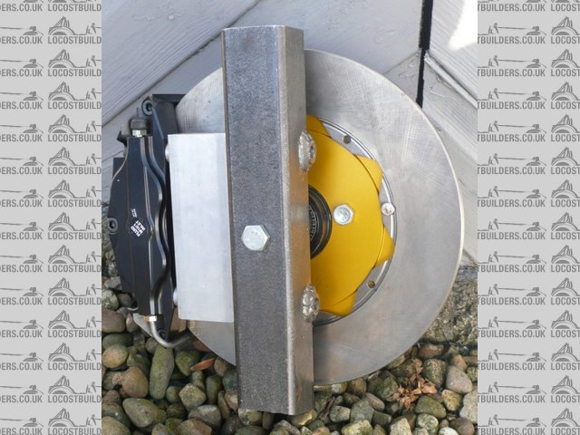
First of all the upright before it gets banjo'd.
 
pre fail
Thanks to Fred for pointing out that the welds were quite proud and that in all probability penetration would be poor. On quick inspection it seemed
that the weld had penetrated as bubbling was apparent on the reverse side but on closer inspection the bubbling was only the mill scale cracking off
and in fact penetration was around 75%.
So I made up a dummy spindle 'cos I did not want to gub a proper one and in order to to reproduce conditions on the car made two locost chassis
brackets complete with crush tubes and put the assembly under my hydraulic press. It was loaded axially as that's where I thought it was weakest.
The brackets were welded to a lump of 12mm plate steel to go under the press.
The hydraulic ratio is 16:1 and the lever ratio is 20:1 giving an overall ratio of 320:1 and it failed at 10kg load. That's 3.2 tonnes. After the
initial failure it continued to deflect at a reduced load of 2 tonnes and I deformed it for a total of 20mm
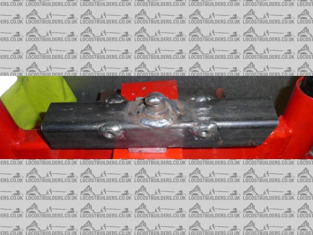
This is an overall pic of the failed upright.
 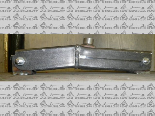
kpi failure
Interestingly the welds did not fail! If anything they are stronger than the tube - and that's with defective welds! See this zoom.
 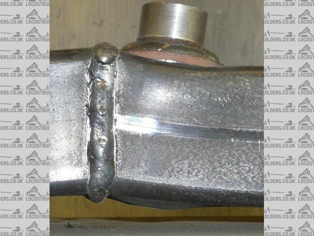
weld condition
You can see the mill scale cracking around the weld but the weld is intact.
Now as for the safety critical bit. It failed at 3.2 tonnes and I reckon that if you put that load into the side chassis rails they would fail long
before that - anyone want to donate a chassis for testing 
Most kit cars are around the 600kg mark 50/50 weight distribution and even if all the weight was on one front upright at 3.2 tonnes lateral load that
would require 10g cornering which is way beyond the tyres capability. For FEA enthusiasts most of the designs I have seen are at 3g with a FOS of 2.
Most interestingly the failure shows obvious ways to strengthen the upright - but do I need to?
As usual input most appreciated
You'd be surprised how quickly the sales people at B&Q try and assist you after ignoring you for the past 15 minutes when you try and start a
chainsaw
|
|
|
|
|
designer
|
| posted on 6/3/11 at 07:38 PM |
|
|
That is certainly strong enough.
|
|
|
Andybarbet
|
| posted on 6/3/11 at 07:47 PM |
|
|
Wow !
I wish i could weld that good and tidy...........my few attempts were diabolical.
Well done that man
Give a man a fish & it will feed him for a day, give him a fishing rod & you've saved a fish.
|
|
|
Ivan
|
| posted on 6/3/11 at 07:51 PM |
|
|
I think you will find that of the two failure modes weld quality is less critical for load mode than for fatigue mode so be careful in thinking the
design is ok based on that test - but then I am no expert and others on here will know a lot better than me.
|
|
|
jacko
|
| posted on 6/3/11 at 07:53 PM |
|
|
How thick is the box wall ?and what size is the box
Did you weld it with co2 for the gas
Jacko
|
|
|
andyd
|
| posted on 6/3/11 at 07:56 PM |
|
|
The metal working DVD I got recently has David Gardinar stating that a MIG weld is stronger than the metal it joins.
I'm not totally surprised that the weld point held up but it's nice to be able to test such safety critical aspects. However, if you made
the same part 10 times, how many times would it fail in the same way or hold up to the same pressure?
It's all about how repeatable the manufacture process is.
You seem to be happy that what you've made stands up to your expectations though.
Andy

|
|
|
JohnN
|
| posted on 6/3/11 at 08:28 PM |
|
|
Was it hinged at both ends?
Were the two hinge brackets welded to a common base?
|
|
|
scudderfish
|
| posted on 6/3/11 at 08:30 PM |
|
|
quote:
Originally posted by v8kid
Now as for the safety critical bit. It failed at 3.2 tonnes and I reckon that if you put that load into the side chassis rails they would fail long
before that - anyone want to donate a chassis for testing
Most kit cars are around the 600kg mark 50/50 weight distribution and even if all the weight was on one front upright at 3.2 tonnes lateral load that
would require 10g cornering which is way beyond the tyres capability. For FEA enthusiasts most of the designs I have seen are at 3g with a FOS of 2.
As usual input most appreciated
You could put a 10g shock load through it clipping a curb.
|
|
|
plentywahalla
|
| posted on 6/3/11 at 09:09 PM |
|
|
quote:
Originally posted by JohnN
Was it hinged at both ends?
Were the two hinge brackets welded to a common base?
Good point .... If both brackets are welded to a common plate thern the weld under test is in increasing compression. You could probably produce
exactly the same result without the two parts of your tube being welded at all!
|
|
|
v8kid
|
| posted on 6/3/11 at 09:22 PM |
|
|
Thanks for the response chaps,
1) Fatigue mode - not quite so. Fatigue depends on how close to the uts you repeat the flexing. With a fos in this case of around 3 I thought fatigue
unlikely to be a problem. Can't remember the exact formulae (shame on me!) but it was an exponential curve IIRC. I can picture it but not quite
recall - can you help out here please?
2) Argoweld was the gas used. its argon with a little CO2. I believe it gives better heat but it's all I have ever used.
3) Repeatable? The blasted thing had defective welds anything else is bound to be better!
4) Common base. Well spotted yes they are and I see your argument. But if one end was free that would not be realistic either. The next test will be
with only one end restrained but there are other factors here I'm thinking about torsion from non symmetrical loading. Still I suppose it is a
worst case test even if it means the rest of the chassis is flapping about in 1 dimension anyhow.
5) 10g thro clipping a kerb. Do you have evidence of this wrt the upright or is 10g a guess? The test was carried out for sustained loads which I
think is more onerous than for transient loads - am I wrong? I seem to remember that a rule of thumb was that transient loads only required half the
fos.
Good stuff chaps the next test will be all the better for your input.
Cheers
[Edited on 6-3-11 by v8kid]
You'd be surprised how quickly the sales people at B&Q try and assist you after ignoring you for the past 15 minutes when you try and start a
chainsaw
|
|
|
Fred W B
|
| posted on 6/3/11 at 11:01 PM |
|
|
Well done Chris on taking the input and the interesting testing. As Ivan says, and in this application desiging for fatigue is more important than the
ability to withstand one big impact load. And understanding fatigue in order to design for it is not easy.
Based on nothing more scientific than "gut feel", I would have liked to have seen some more reinforcing around the point where the axle
connects to the tube, and now your testing has pointed out where it could be placed. Some square plates welded horiziontally into the tube (across the
section of the tube) above and below the axle point would help a lot. You would have to weld these in before you weld the 2 sections of the upright
together. I would also suggest "doubler" plates on the front and back faces of the tube in this area. You could take these doublers across
the weld to reinforce it, and this would make the weld integrity less critical.
You have to also consider where the steering arms will attach, and make similar provisions there.
Cheers
Fred W B
[Edited on 6/3/11 by Fred W B]
You can do it quickly. You can do it cheap. You can do it right. Pick any two.
|
|
|
v8kid
|
| posted on 6/3/11 at 11:33 PM |
|
|
Checking up on my recollections by searching t'internet shows that as a rough guide for low carbon steel as in (a) the fatigue limit is usually
about 40% of the tensile strength. In principle, components designed so that the applied stresses do not exceed this level should not fail in service.
Or in other words a fos of 2.5 - assuming that the welds were properly done in the first place!
 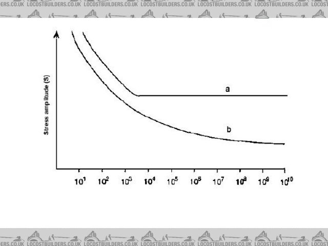
ms fatigue a
I'm a bit surprised my memory was in the right ballpark - must be a fluke! This assumes of course that the fatigue is always at the same high
limit. In practice of course the majority of loading is well below this adding to the safety. I'm really comfortable about the welds with the
caveat that I need to retest with one free end.
Loadings on the steering arms will be considerably less - the track rod ends will bend first. Also the steering arms will bolt on to the same holes as
the calipers which spreads the load and makes one upright suitable for both sides
low kpi rear
I also have a feeling that doubling up is not necessary - why add strength where it is not required? Do I really need to cater for loads in excess of
10g - where will it end?
Other posts - I think by RPM magazine talked about loadings of 3g including fos!!! However it's my neck and I've had one heavy crash into a
tyre wall at full throttle coming out of paddock bend so 10g is fine for me.
Still my inclination is to reduce the wall thickness and still meet this spec. In some respects the weakness is the bolted stub axle if it were welded
the strength should be greater allowing thinner wall thickness. Perhaps in combination with Fred's doublers this might be the way to go. Then
again would it expose my dodgy welding!
Also note the retaining bolts. They are 10mm mild steel studding as I wanted to see what would happen to them.
Destructive test 2 coming shortly but I want more input first please chaps as there is a limit to how many of these things I want to make and trash
Cheers!
David
You'd be surprised how quickly the sales people at B&Q try and assist you after ignoring you for the past 15 minutes when you try and start a
chainsaw
|
|
|
Fred W B
|
| posted on 6/3/11 at 11:59 PM |
|
|
Fair enough Chris.
In your test you applied a vertical load with the upright horizontal, so an axial (cornering) load?
I would be interested to see how the upright would behave if it were positioned vertically and a vertical load applied to the lever arm that the axle
forms ("Bump" load)
Cheers
Fred W B
You can do it quickly. You can do it cheap. You can do it right. Pick any two.
|
|
|
v8kid
|
| posted on 7/3/11 at 01:06 AM |
|
|
Fred,
I'm not sure why? Wouldn't the bending load be less that way?
You'd be surprised how quickly the sales people at B&Q try and assist you after ignoring you for the past 15 minutes when you try and start a
chainsaw
|
|
|
coyoteboy
|
| posted on 7/3/11 at 01:38 AM |
|
|
Just a few thoughts...
In the real item:
The two ends are not constrained to each other.
The load will not be axial (primarily).
You can't really size for clipping kerbs as even a road car will deform on kerb clipping.
?
|
|
|
v8kid
|
| posted on 7/3/11 at 09:19 AM |
|
|
Fair enough.
1) So in the next test only one end will be constrained.
2) Agreed the loading is not 100% axial there is a couple in there. My hydraulic press bed is not wide enough to reproduce the couple any suggestions
how I can test it?
3) This is the crux of the matter! What loading do I size for?
I've got to do some work for a while but I'll do some sums on 2) and see what proportion the couple is to the axial load and post it if
anyone is interested.
Cheers!
David
You'd be surprised how quickly the sales people at B&Q try and assist you after ignoring you for the past 15 minutes when you try and start a
chainsaw
|
|
|
onenastyviper
|
| posted on 7/3/11 at 01:26 PM |
|
|
Just a thought: the way a load is just as important as to how large it is.
The load, its direction, magnitude, rate of change etc. all determine how a component will perform.
|
|
|
alistairolsen
|
| posted on 7/3/11 at 02:18 PM |
|
|
2 thoughts on tests:
1) bottom mount restrained, top mount on a roller, push up on the stub axle end to simulate landing hard on the front wheels.
2) same again the other way up to simulate the bending induced in the stub axle by a cornering force pushin in on the base of the wheel and hence
pulling down on the end of the stub axle.
(I know my terminology is failing badly just now but hopefully you get what I mean.)
My Build Thread
|
|
|
v8kid
|
| posted on 7/3/11 at 02:19 PM |
|
|
Great minds must think alike I was mulling that very thought over in my head!
In attempting to make sense of this I realised all the forces act initially at one point - the tyre contact patch. Moreover for all horizontal forces
they are limited by the friction of the tyre. Most references seem to indicate that with moderate to low aero the tyre will only give 1.4g in any
horizontal direction - call it 1.5g to be safe and make sums easy.
Now the exception is crashing the blessed thing but then the tyre and wheel are going to be gubbed anyhow so what does it matter if the upright
deforms?
Also by the marvels of the parallogram of forces I can say that the upright has either 1.5g braking (fore/aft) or 1.5g cornering (side/side) but not
both at once. If its braking and cornering it can only have 1.5/root2 or 1.06g in both directions to give a resultant force of 1.5g at 45 degrees to
the direction of travel.
So if I test at 1.5g fore/aft and 1.5g side/side I have covered most bases. Those who have been paying attention might wonder how the fore/aft force
can be transmitted through a revolving wheel - I know i was puzzled until I realised that it is through the brake calliper mounts - i.e. two 12mm
bolts. As these never fail in my experience I think this puts the magnitude of these forces in context.
This still leaves the up and down forces. But hang on a mo the tyre is absorbing most of the transient high shock forces and the spring/damper is
taking the rest. Also the vertical forces are acting near enough in compression up the upright so they will be small in comparison. Also bear in mind
that ALL this force is taken in one 12mm bolt at the bottom on the coilover - more contextual evidence.
To all these forces add in a factor of safety of 3 to take care of fatigue and that gives a loading of 4.5g horizontally. This translates into a force
of 1350kgf (13.2KN or 1.3 tonnes) plus a torque couple at the stub axle of 900kgf/m (8.8knm).
Hmm!! Coyoteboy has a point - that torque couple is substantial - well spotted that man!
OK I can modify my Hydraulic press to simulate the 1.5g side force and couple or the braking force and couple but don't have enough upright
material to do both.
Any preferences?
You'd be surprised how quickly the sales people at B&Q try and assist you after ignoring you for the past 15 minutes when you try and start a
chainsaw
|
|
|
v8kid
|
| posted on 7/3/11 at 02:22 PM |
|
|
Sorry Alistair our posts crossed. Yes I'd like to do that but how do I restrain it in the hydraulic press! when simulating the bump force?
You'd be surprised how quickly the sales people at B&Q try and assist you after ignoring you for the past 15 minutes when you try and start a
chainsaw
|
|
|
Fred W B
|
| posted on 7/3/11 at 02:29 PM |
|
|
quote:
that torque couple is substantial -
Thats why I suggested a vertical load applied to the axle with the upright vertical, to "twist" the axle in the upright.
Cheers
Fred W B
You can do it quickly. You can do it cheap. You can do it right. Pick any two.
|
|
|
Livio
|
| posted on 8/3/11 at 06:59 PM |
|
|
Grat for this very interesting topic. I am curious about the outcome.
I'm thinking about your steering arm mount.
Only those small circular areas will mate? If so, will it hold enough inspite that the force is coming from the worst direction concerning the two
bolting points on the upright?
Livio
|
|
|
alistairolsen
|
| posted on 9/3/11 at 11:31 AM |
|
|
quote:
Originally posted by v8kid
Sorry Alistair our posts crossed. Yes I'd like to do that but how do I restrain it in the hydraulic press! when simulating the bump force?
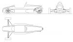
Excuse the poor drawing:
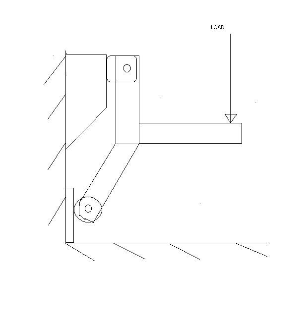
You need to replace one bush with a roller and bolt the top on place, having made a jig with sufficient stiffness to support the assembly.
My Build Thread
|
|
|
v8kid
|
| posted on 9/3/11 at 03:42 PM |
|
|
Thanks Alistair I see where you are coming from now. I don't have the materials to build a jig stiff enough - I think it would require 6x6 steel
angle - but I could fabricate some sort of restraint on the press upright I think.
However the next test will be a lateral force test combined with torsion as I think that is the greater force. If I have enough materials left over
I'll try the vertical loading test.
The reason I think the lateral force is higher than the vertical force is
[
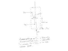 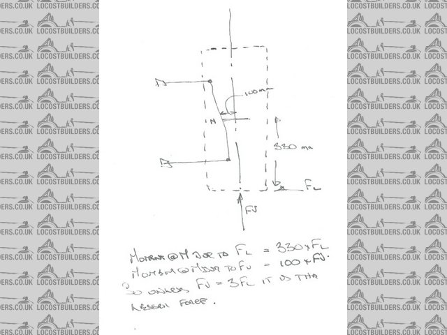
fvfl
Cheers!
You'd be surprised how quickly the sales people at B&Q try and assist you after ignoring you for the past 15 minutes when you try and start a
chainsaw
|
|
|
v8kid
|
| posted on 12/3/11 at 11:26 AM |
|
|
1 step forwards two steps back......
First the success. Looking closely at the failure I noticed that the hole that the stub axle fitted into was very slack. Strange cos it was a tight
fit before the test. I reasoned that in deforming the metal had pulled away from the hole.
By the same reasoning welding the stub axle in should strengthen the upright. Now I know there has been lots of discussion about how and in what
direction to load the upright but in order to compare I loaded it the same way as before. I did not even bother with the brackets after all they had
held up before! So under the press it went. The load was applied axially on to the dummy stub axle and the body was kept clear of the press bed at the
extremities by a couple of lengths of straight steel bar.
There was room for the body to deform 20mm which I reckoned was enough for a quick test. The dummy stub axle was welded on both sides and Fred will be
pleased to see better welds this time. I have a great excuse for the old welds - the welder main power lead to the torch was frayed 90% through -
still I should have noticed earlier.
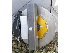
welded threequarters
Result! This time it took 10 tonnes and did not budge an inch. Unfortunately I could not load it any higher as the press failed due to some
over-exuberance earlier trying to press a 3rd gear off the lay-shaft weakening the press cross arm which bent! I should hastily point out that this
photo was after the event and no I was not daft enough to test it with a lump of ally supporting it!
So the press has to be repaired - no big deal I'll do it this afternoon. I was most impressed at the earlier event which weakened it 'cos
there were 2 of us hanging on a 3' bar and the cheapo Chinese bottle jack did not blow a seal as expected. The 3rd gear is still on the layshaft
apparently it takes a 50 tonne press and then it goes with a BIG bang - so I am told.
Also using a set of bathroom scales to measure force was inconvenient as I had to stand on a stepladder to see the scale so i bought a hanging balance
off the bay and hopefully it will be here next week.
So with this knowledge the Mk2 upright is as below.
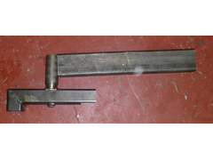 
lever
The dummy stub axle is welded both sides and longer so I can weld a bar on to it which is shown in position but not welded yet.
The angled end of the upright is where the top ball joint or rod end in my case will go. I changed the design to enable uprights with different
kpi's to be made from the same design simply by drilling the mounting holes in different positions.
So for testing the idea is to support the upright at the top balljoint end with a bracket, support the bottom balljoint end on a suitably sized lump
of steel with grease lathered on it and press down on the bar at a distance from the stub axle equal to the tyre contact position. Clear as mud?
I'll put a pic before and after testing on the press next time.
Ah! the reason I have not welded the lever on to the stub axle is I have not decided on the angle to weld it - should be the same as the caster angle
I think but I have offset the stub axle 9mm so I need to think on it.
Thanks for the support and U2U's
Cheers!
You'd be surprised how quickly the sales people at B&Q try and assist you after ignoring you for the past 15 minutes when you try and start a
chainsaw
|
|
|