sgraber
|
| posted on 24/5/03 at 01:55 AM |

|
|
Inspired to... sit and design
All the latest hulabaloo re; Alans GRP got me inspired to work on my body design. Any comments?
Steve G 
 
Rescued attachment radiosityrender1.jpg
Steve Graber
http://www.grabercars.com/
"Quickness through lightness"
|
|
|
|
|
Alan B
|
| posted on 24/5/03 at 02:23 AM |
|
|
Steve...I like it.....
Look's you'll need the 90mm Hellas too...
It's got that kinda professional concept show car look....
|
|
|
MattWatson
|
| posted on 24/5/03 at 02:49 AM |
|
|
I like it as well! Excellent job.
What are you using for your 3d program?
Matt Watson
--------------------------------
VW 1.6L SOHC Turbo Mid engined car
http://members.shaw.ca/wavindustries/
|
|
|
sgraber
|
| posted on 24/5/03 at 03:31 PM |
|
|
Thanks.
Alan, can you give me a time estimate for coming out to AZ to build this for me?  
Alternately, can you see from this view what parts of this body are 'non-manufacturable'? I simply don't have any practical
experience with mold making. <YET....>
I am using 3DSMax that jpg is really low quality, I am using radiosity lighting which really cleans up the shadows.
Steve Graber
http://www.grabercars.com/
"Quickness through lightness"
|
|
|
Alan B
|
| posted on 24/5/03 at 04:33 PM |
|
|
Steve, from just this one view I don't see anything blatantly non-manufactureable.
Some corners may need slightly bigger rads.....and some consideration will be needed regarding where the moulds split etc....but overall should be
do-able...
|
|
|
Rorty
|
| posted on 25/6/03 at 05:41 AM |
|
|
sgraber:
quote:
Alans GRP got me inspired to work on my body design. Any comments?
Yes, it looks like Alans GRP!
And very nice it is too!
Cheers, Rorty.
"Faster than a speeding Pullet".
PLEASE DON'T U2U ME IF YOU WANT A QUICK RESPONSE. TRY EMAILING ME INSTEAD!
|
|
|
Spyderman
|
 posted on 25/6/03 at 12:22 PM posted on 25/6/03 at 12:22 PM |
|
|
Mmm!
I like it!
Any chance of a rear 3/4 view?
Terry
Spyderman
|
|
|
kingr
|
| posted on 25/6/03 at 12:31 PM |
|
|
Any comments? err. yup, one, your far too damn good at 3DSM, and two you have far too much time on your hands!!
Seriously though, looks the business, should look even better in the flesh.
Kingr
|
|
|
kingr
|
| posted on 25/6/03 at 12:32 PM |
|
|
The back end reminds me of the Porsche Carrera GT.
Kingr
[Edited on 25/6/03 by kingr]
|
|
|
Jon Leeper
|
| posted on 25/6/03 at 04:41 PM |
|
|
Nice, Looks a bit like the Shelsley T2 Are you going for opening doors?
|
|
|
sgraber
|
| posted on 26/6/03 at 03:13 AM |
|
|
Yeah, I keep thinking that it will have 1/2 doors that hinge up at the front. The frame has been built so that doors can be put on. But probably the
prototype will be a more simple 'sit on the ledge and drop in' kinda car. With a removable steering wheel.
I think I kinda suck at 3DS, but that's because I have friends like this. http://www.watsonstudios.com/
I haven't finished the look of the rear, but think Opel Speedster.
Shelsley T2? A car with excellent driving dynamics, but I am hoping to get more of an edgey look to mine.
Steve Graber
http://www.grabercars.com/
"Quickness through lightness"
|
|
|
Alan B
|
| posted on 26/6/03 at 11:53 AM |
|
|
Steve, I just checked the link....VERY nice work indeed.....
Also, checked out your latest update.....coming on very well....soon be finished...
|
|
|
Jon Leeper
|
| posted on 26/6/03 at 04:14 PM |
|
|
I am also thinking of allowing for doors, your avatur shows a roll over bar, is this still a feature or are you also thinking of the twin hoop route?
As for 3DSM I had a friend try and sort out something from my sketches and it was no half as good as yours  Still if I had the money then I could
employ your friends to give me a really profesional look! Oh well back to the old pencil and paper routine Still if I had the money then I could
employ your friends to give me a really profesional look! Oh well back to the old pencil and paper routine
Keep up the good work it is enjoyable watching everyone else progress!
Jon Leeper
If in doubt, blow it up!
|
|
|
sgraber
|
| posted on 26/6/03 at 04:30 PM |
|
|
Alan my friend, thanks. I am still dreading the bodywork tho. It will be years probably before that is finished.
The rollbar was just formed this morning. It is 2" round .120 wall and I expect to be covering it with a fiberglass fairing as shown in my
avatar. It bolts on to the car at the superstructure. Removable for different purposes - street cruising:no rollbar, canyon carving:rollabr, track
days:rollbar with x-brace to windshield.
Steve
PS - Even I can't afford my friend Jon's animation/illustration services. He is a multiple Emmy winner and lives very comfortably with
freelancing projects all over the world... Some guys.... It's ok tho - I stole his girlfriend who then became my wife!
Steve Graber
http://www.grabercars.com/
"Quickness through lightness"
|
|
|
cymtriks
|
| posted on 26/6/03 at 09:45 PM |
|
|
the chassis
Steve,
I've taken a look at the pics on your site and it looks as if the rear chassis stiffness would benefit from some extra triangulation. The pics
don't show any around the front, back, bottom or top.
I doubt if a diagonal would fit acros the bay as it would probably snag the engine but a V brace might if put sideways and a Y brace is also
possible.
Adding triangulation across the front and back of the bay looks fairly striaght forwards and will help tie the sides together.
I like the styling by the way.
Chris
|
|
|
sgraber
|
| posted on 26/6/03 at 10:05 PM |
|
|
Chris, Thanks very much for those comments. That's exactly the type of comment I am hoping to get off the message board! Take a look at the
attached image and tell me if this is a good start?
I plan on making it a removable 'v-brace' starting from the center/front of the engine bay and travelling back to both rear corners. In this
image only one side of the 'V' is finished.
As you mentioned, major triangulatation is still missing from the engine bay around the sides and back, and another brace will be added above the
engine across the transmission to that side motor mount.
Thanks again and please feel free to send diagrams with ideas.
 
Rescued attachment Bala06-23-03 007.jpg
Steve Graber
http://www.grabercars.com/
"Quickness through lightness"
|
|
|
sgraber
|
| posted on 26/6/03 at 10:16 PM |
|
|
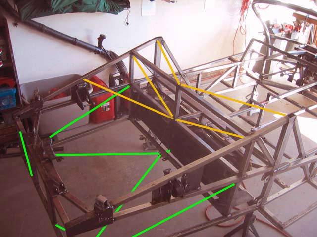
This is what I am thinking regarding additional bracing. The green lines are lower. the orange lines are upper. Anyone care to comment on
this?
Rescued attachment BalaBracing.jpg
Steve Graber
http://www.grabercars.com/
"Quickness through lightness"
|
|
|
Alan B
|
| posted on 27/6/03 at 12:16 AM |
|
|
Steve, this is my engine bay for reference.
I still have some diagonals to put in but may give some ideas........

|
|
|
Rorty
|
| posted on 27/6/03 at 04:36 AM |
|
|
sgraber, That looks about spot on. I like what you're doing with it all.
Alan, I just noticed in that pic you just posted, the rear suspension links look like they will bind. Surely you would need some form of spherical
rodend in that application? Or are they a soft rubber bush, and you don't envisage much vertical wheel movement? Am I missing something?
Cheers, Rorty.
"Faster than a speeding Pullet".
PLEASE DON'T U2U ME IF YOU WANT A QUICK RESPONSE. TRY EMAILING ME INSTEAD!
|
|
|
Alan B
|
| posted on 27/6/03 at 12:44 PM |
|
|
Hi Rorty,
They are poly bushes at the frame ends and rod ends at the other end.
The twist is minimal, but is allowed for.
Only the the top front wishbone has hard (rotating) bushes.
|
|
|
cymtriks
|
| posted on 28/6/03 at 02:19 PM |
|
|
Steve,
I've done a quick analysis of tubes around your engine bay. I saved time by grafting your engine bay region to the rear of my Lotus 23 model to
give a feel for how it works.
With only the upper side diagonals (as shown in your website photos) 900ftlbs per degree.
With lower V brace as shown in your post, diagonals across the rear, diagonals across the front of the engine bay (in the panel behind the petrol
tank), and a net work of diagonals arond the top of the engine bay 1800ftlbs.
The yellow tubes going to the top of the chassis (your post) probably don't do much for stiffness.
The yellow engine bay diagonal in your post needs to continue right round the engine. I'll try and post a diagram shortly.
Chris
|
|
|
cymtriks
|
| posted on 28/6/03 at 02:44 PM |
|
|
picture
Rescued attachment steveschassis.JPG
|
|
|
cymtriks
|
| posted on 28/6/03 at 03:03 PM |
|
|
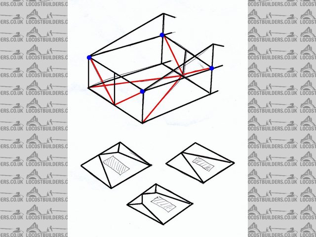
That's the diagram done.
The engine bay top triangulation is shown in the three small views. The shadded area is roughly where the engine is. It doesn't matter much
which option you choose, pick the one that fits best round your engine.
The red tubes in the main view are the other tubes that I added to the engine bay to get the increase in stiffness quoted above.
There is a difference between your chassis and my analysis in the rear of the bay. You have three rectangles across it and your last post suggested
adding diagonals to two of them. My model has two rectangular spaces and two diagonals. Fitting a diagonal, X brace, V brace or welded in panel
accross the central panel of your rear frame will make its behaviour similar to my analysis.
Alan,
Your chassis would also be stiffened up by tubes across the top of engine bay similar to those shown in the three small views.
Regards
Chris
|
|
|
cymtriks
|
| posted on 28/6/03 at 03:11 PM |
|
|
I can't find the edit function!
I forgot to say that the diagonals around the top of the engine bay connect the blue dots in the main picture. They do not connect to the tops of the
triangular towers on the chassis sides.
Can anyone show me where the edit function is?
|
|
|
Alan B
|
| posted on 28/6/03 at 04:19 PM |
|
|
More than likely I'll have a bolt on top brace...fastened back to my top corner gussets...I'll have to see how the space works out....
Plus, a bolt on one can be changed for different engines.
|
|
|


