Sean
|
| posted on 7/4/04 at 01:08 PM |

|
|
A picture! Correct or not?
I have linked my 4 pots as shown, but could someone tell me if I have used the right combination of holes. Thanks
 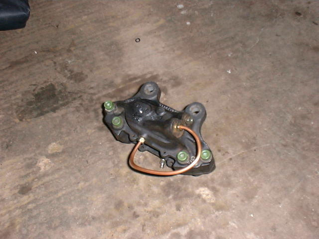
Rescued attachment DSCF0013.JPG
|
|
|
|
|
gjn200
|
| posted on 7/4/04 at 03:49 PM |
|
|
Can't really tell from the piccy, but looks wrong to me. Any extra pipe would be from one side of the calliper to the other(if not done
internally), and both sides should have a bleed nipple.
<- Me!
|
|
|
Sean
|
| posted on 7/4/04 at 03:53 PM |
|
|
That seems to be the problem, knowing exactly which ones to join. It would appear to have been a common enough mod and yet finding out how it was done
is proving difficult. I guess I need the escort boys of the 70's who did it most!
|
|
|
NS Dev
|
| posted on 7/4/04 at 05:37 PM |
|
|
from one side to the other on the caliper is indeed done internally. What you need to do is link the two "top" holes (the two together)
and connect this link to the new "supply". I.e. put in a T-piece and supply them both together. I think the hole near the pads that you
have connected to is the other bleed screw hole. if you look at the two holes together at the "top" of the caliper, one supplies the
bottom pair of pistons, the other the top (which is the idea for safety on the princess etc) these two need connecting, the flow from one lower piston
or upper piston to it's opposite number is done internally.
|
|
|
Sean
|
| posted on 7/4/04 at 06:27 PM |
|
|
Sean
It sounds to me as if it is perhaps going to be easier to have a t piece at the chassis end and have two braided hoses going in as it is suppose to,
as I understand it. Mmm!!! More expense. Besides there is not alot of room round 13 inch rims to do great deal.
|
|
|
steve m
|
| posted on 7/4/04 at 07:35 PM |
|
|
Sean I have u2u
I have this set up and a I belive it to be the same as your picture
I presume that i got it right as my brakes are about 50% better than the old m16 setup
regards
steve
|
|
|
Sean
|
| posted on 7/4/04 at 08:42 PM |
|
|
Any chance you could double check that please Steve?
|
|
|
steve m
|
| posted on 7/4/04 at 09:37 PM |
|
|
sean
check your u2u
steve
|
|
|
steve m
|
| posted on 8/4/04 at 03:44 PM |
|
|
Sean
my top conection goes from the one nearset the hub and the same lower one as yours
were your top pipe goes in is were my feed from the mastercyl goes into
I took my setup from an old for transit haynes manual
steve
|
|
|
Sean
|
| posted on 9/4/04 at 07:21 AM |
|
|
Well this is how it looks now. I have used a t piece and brake pipe to make up this, which enables the use of both intakes. ( thanks to Andy and his
brake tool )It's tight but not as close as it looks. Not ideal, but at least functional. Shame about the horrible wishbones. Need to be
cylindrical!
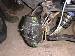 
Rescued attachment DSCF0015.JPG
|
|
|