edthedrummer
|
| posted on 27/2/14 at 11:23 PM |

|
|
Calculating Castor, Wishbone mounting help required...
Evening all!!
I've posted already this evening in the Chassis section about relocating and replacing a couple of front suspension bracket related tubes.
Now I have a question relating to Castor.
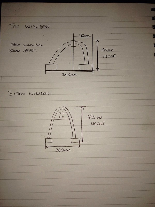
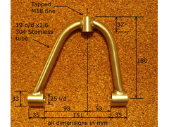
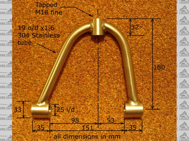
How do i calculate the castor that my wishbones will provide? Below is a hand drawn diagram of my wishbone dimensions. I am currently trying to fathom
out exactly how i calculate where abouts the wishbones mount in relation to each other on the chassis, and now want to know if i will have enough
castor angle, or if its possible to have too much?
Untitled by Edward Ashton, on
Flickr
The top wishbone has a 30mm offset towards the rear of the car as can hopefully be made out by my scribble.
How do you work out precisely where abouts the wishbone needs to mount above the lower wishbone?
Help guys!!
Ed
|
|
|
|
|
mark chandler
|
| posted on 27/2/14 at 11:33 PM |
|
|
It depends upon where your suspension brackets are mounted, you are only showing half the story.
You need to make sure that your shocks do not foul the top wishbone as well.
|
|
|
edthedrummer
|
| posted on 27/2/14 at 11:37 PM |
|
|
My suspension brackets are being replaced, none of them are aligned correctly, the holes through the brackets are not parrallel to the centre line of
the car.
|
|
|
v8kid
|
| posted on 28/2/14 at 06:38 AM |
|
|
If your bottom wishbone is symmetrical and if you mount the wishbones on the car with their mounting points equidistant from a vertical line the top
of your upright will be 10mm further back. The caster angle is arctan 10/(upright height)
Clearly you can alter caster simply by moving the wishbone fore/aft relative to each other.
Really you need a lot more measurements 
Mounting points are not always parallel to the center line you know! Are you sure the existing is wrong?
Cheers!
You'd be surprised how quickly the sales people at B&Q try and assist you after ignoring you for the past 15 minutes when you try and start a
chainsaw
|
|
|
edthedrummer
|
| posted on 28/2/14 at 07:37 AM |
|
|
Thanks for the reply!!
Could you explain how it comes to be 10mm further back? I presume by further back you mean towards the rear of the car?
What other measurements should I be looking to do to help?
The original book dimensions were for mounts parallel to the centre line though. It's possible to pass a piece of 12mm threaded rod easily
through the mounting eyes of the wishbones, but the holes in the brackets are not lined up.
Ed
|
|
|
edthedrummer
|
| posted on 28/2/14 at 07:42 AM |
|
|
Ahhhh hang on!!
If my top wishbone is 240mm wide from the outside of the bushes, the true centreline is 120mm, with the measurement I took to the middle of the
ballpoint tube being 110mm, this is where the 10mm further back comes from!
So my tired minded calculation of 30mm offset is quite frankly, poop.
|
|
|
Slimy38
|
| posted on 28/2/14 at 08:48 AM |
|
|
quote:
Originally posted by edthedrummer
but the holes in the brackets are not lined up.
That's the bit that worries me more than anything else, I can imagine that putting unpleasant stresses on the wishbones.
|
|
|
v8kid
|
| posted on 28/2/14 at 09:33 AM |
|
|
quote:
Originally posted by Slimy38
quote:
Originally posted by edthedrummer
but the holes in the brackets are not lined up.
That's the bit that worries me more than anything else, I can imagine that putting unpleasant stresses on the wishbones.
Yikes! Yes Slimey38 is right you should be able to put a bit of threaded rod through the brackets on the car - that is how I welded them on my car I
bolted them together at the required spacing to make the lining up easier. However they do not have to be parallel to the centerline of the car
although the sums get more difficult as you end up with caster gain on deflection. Most are in fact parallel.
I presume it is just caster you are concerned with. See last post re calculating it most people are 4 to 6 degrees not many more than 9 degrees. You
can make it adjustable by using wider brackets. At 10mm offset with an upright height of 250mm say from balljoint center to center the caster will be
approx 2.4degrees. By shimming say 5mm further back you can adjust this to 3.5 degrees. Most wishbones do not have their centerlines on the same
vertical the top is usually further back. Anyhow I'm sure you get the picture if you want 6 degrees caster the top balljoint has to be 26mm
further back than the lower balljoint.
PS 250mm is my upright others may be quite a bit different
You'd be surprised how quickly the sales people at B&Q try and assist you after ignoring you for the past 15 minutes when you try and start a
chainsaw
|
|
|
Slimy38
|
| posted on 28/2/14 at 10:02 AM |
|
|
quote:
Originally posted by v8kid
Yikes! Yes Slimey38 is right you should be able to put a bit of threaded rod through the brackets on the car - that is how I welded them on my car I
bolted them together at the required spacing to make the lining up easier. However they do not have to be parallel to the centerline of the car
although the sums get more difficult as you end up with caster gain on deflection. Most are in fact parallel.
There is also the consideration that the original locost design (the '£200' book) the lower brackets don't have an easily
identifiable line between the two, the FU tubes are in the way. I carried on reading the book after posting that comment, and they recommend using the
built up wishbones themselves to mount the brackets. I'm guessing that is the primary reason why things are cock-eyed, I'd be tempted to
figure out another way of lining things up.
|
|
|
mark chandler
|
| posted on 28/2/14 at 10:21 AM |
|
|
Brackets like this
NSF bare tube chassis Nov 2005
Once they are in place make the bottom wishbone uniform, for the top bone the centre line should be around 7-10mm behind the centreline.
I would only add the shock brackets once you have the bones in place to make sure they do not foul the top bone.
Regards Mark
|
|
|
edthedrummer
|
| posted on 1/3/14 at 12:33 AM |
|
|
quote:
Originally posted by v8kid
quote:
Originally posted by Slimy38
quote:
Originally posted by edthedrummer
but the holes in the brackets are not lined up.
That's the bit that worries me more than anything else, I can imagine that putting unpleasant stresses on the wishbones.
Yikes! Yes Slimey38 is right you should be able to put a bit of threaded rod through the brackets on the car - that is how I welded them on my car I
bolted them together at the required spacing to make the lining up easier. However they do not have to be parallel to the centerline of the car
although the sums get more difficult as you end up with caster gain on deflection. Most are in fact parallel.
I presume it is just caster you are concerned with. See last post re calculating it most people are 4 to 6 degrees not many more than 9 degrees. You
can make it adjustable by using wider brackets. At 10mm offset with an upright height of 250mm say from balljoint center to center the caster will be
approx 2.4degrees. By shimming say 5mm further back you can adjust this to 3.5 degrees. Most wishbones do not have their centerlines on the same
vertical the top is usually further back. Anyhow I'm sure you get the picture if you want 6 degrees caster the top balljoint has to be 26mm
further back than the lower balljoint.
PS 250mm is my upright others may be quite a bit different
Yes sorry, perhaps I didn't make it clear, the wishbone brackets are not correctly aligned, but whilst I am rebuilding the car, I want to re-do
them so that they are. This is why I am wanting to know the caster calculations so that I can ensure the brackets are positioned correctly in
accordance with the dimensions of my wishbones.
V8Kid, can you explain 'arctan' further? My upright height (measured from outside of one ballpoint mount to outside of t'other) is
170mm.
Using some basic trigonometry, imagining it all as a triangle, the upright gives a length of 170mm, offset gives 10, meaning the height up the
centreline of the lower ballpoint is 170.2. Assuming that one angle in the triangle is a right angle, the angle the upright leans back from vertical
is 3.4 degrees?
I know it's quite a cack handed way of explaining this, but can you clarify that I am along the right lines? Or is there just no hope!!
Ed
|
|
|
big_wasa
|
| posted on 1/3/14 at 08:59 AM |
|
|
The reality is that you will only be able to change the castor by changing either set of wish bones, usually the top.
In theory you can move the brackets to give you the castor you want. The reality is that if you try this the brackets will be hanging in mid air and
it makes the shock mounting much harder. It moves the bottom of L1+2 ?? in board. Ive been there with my firs chassis and I ended up having to brace
across to give the brackets something to sit on. Second chassis I mounted as per book and made my own wishbones.
To set my brackets I made a jig, lots of posts.
 
first chassis by moving the brackets
Second chassis by remaking the bones.
|
|
|
907
|
| posted on 1/3/14 at 09:38 AM |
|
|
Hi.
When I did mine I worked to the book. Brackets positioned, and wishbones made, all book dims.
However,
the car drove like it had a mind of its own and would dive off line dependant on road camber if I let go of the steering wheel.
I find that measuring in degrees is not possible using normal garage tools so I prefer to work with dimensions rather than angles.
As my brackets were welded to the chassis using a rod method similar to Wasa's above and were parallel to the chassis centreline
I opted to re-make the top bones to increase castor.
I altered my jig to change the book figure to 22mm. (pic shows an old bone on top of the new one)
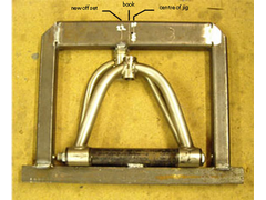 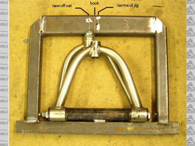
Rescued attachment wb-jig-s.jpg
This results in castor that when viewed from above looks like :-
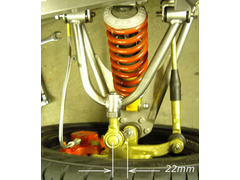 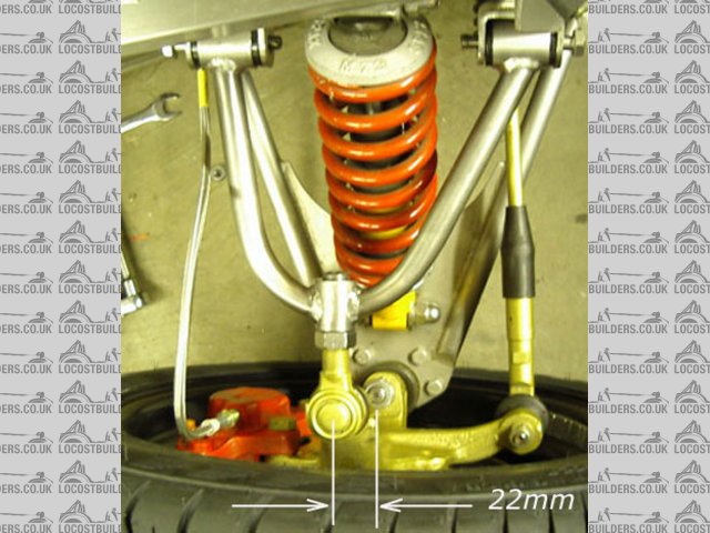
Rescued attachment Wishbones-s-22.jpg
Top bones were made to these dims.
Wish bone dims extra castor
HTH
Paul G
[Edited on 1/3/14 by 907]
|
|
|
v8kid
|
| posted on 1/3/14 at 11:14 AM |
|
|
quote:
Originally posted by edthedrummer
quote:
Originally posted by v8kid
quote:
Originally posted by Slimy38
quote:
Originally posted by edthedrummer
but the holes in the brackets are not lined up.
That's the bit that worries me more than anything else, I can imagine that putting unpleasant stresses on the wishbones.
Yikes! Yes Slimey38 is right you should be able to put a bit of threaded rod through the brackets on the car - that is how I welded them on my car I
bolted them together at the required spacing to make the lining up easier. However they do not have to be parallel to the centerline of the car
although the sums get more difficult as you end up with caster gain on deflection. Most are in fact parallel.
I presume it is just caster you are concerned with. See last post re calculating it most people are 4 to 6 degrees not many more than 9 degrees. You
can make it adjustable by using wider brackets. At 10mm offset with an upright height of 250mm say from balljoint center to center the caster will be
approx 2.4degrees. By shimming say 5mm further back you can adjust this to 3.5 degrees. Most wishbones do not have their centerlines on the same
vertical the top is usually further back. Anyhow I'm sure you get the picture if you want 6 degrees caster the top balljoint has to be 26mm
further back than the lower balljoint.
PS 250mm is my upright others may be quite a bit different
Yes sorry, perhaps I didn't make it clear, the wishbone brackets are not correctly aligned, but whilst I am rebuilding the car, I want to re-do
them so that they are. This is why I am wanting to know the caster calculations so that I can ensure the brackets are positioned correctly in
accordance with the dimensions of my wishbones.
V8Kid, can you explain 'arctan' further? My upright height (measured from outside of one ballpoint mount to outside of t'other) is
170mm.
Using some basic trigonometry, imagining it all as a triangle, the upright gives a length of 170mm, offset gives 10, meaning the height up the
centreline of the lower ballpoint is 170.2. Assuming that one angle in the triangle is a right angle, the angle the upright leans back from vertical
is 3.4 degrees?
I know it's quite a cack handed way of explaining this, but can you clarify that I am along the right lines? Or is there just no hope!!
Ed
arctan is just the inverse of tan ( going the other way) - you are doing it fine its just names Wasa and 907 describe it better than I can.
One point its handy to use angles rather than measurements then you can compare to different cars. e.g. different upright heights. An advantage of
more caster apart from stability is it adds negative camber to the outside wheel on a turn so you don't have to run so much negative static
camber making braking on the front better.
Cheers!
You'd be surprised how quickly the sales people at B&Q try and assist you after ignoring you for the past 15 minutes when you try and start a
chainsaw
|
|
|