Pseicho
|
| posted on 20/1/04 at 05:02 PM |

|
|
Torsional Rigidity/Stiffness?!
I want to design my own frame and analyse it with FEA. Now I see a lot of you talking about torsional rigidity, but I can't find anywhere how to
calculate it.
I've got MSC Marc Mentat (an FEA calculation program) and Unigraphics. Can anyone explain to me how to do it?
|
|
|
|
|
TheGecko
|
| posted on 20/1/04 at 11:58 PM |
|
|
In Australia, our chassis are actually tested for torsion and beam strength. The test method for torsion is to rigidly fix the rear end of the
chassis through the suspension mounts. The front end is allowed to pivot on a central fulcrum and a beam is mounted across the chassis through the
suspension pickups. Weight is added to the end of the beam until the desired test torque is reached (or the chassis fails!  ). Dial indicators are
used to measure deflection at various points along the length of the chassis and the results interpolated to come up with a stiffness figure. For
four cyclinder engines we have to meet or exceed 4000Nm/degree. ). Dial indicators are
used to measure deflection at various points along the length of the chassis and the results interpolated to come up with a stiffness figure. For
four cyclinder engines we have to meet or exceed 4000Nm/degree.
In an FEA program you can simulate the test process by creative use of constraints and applied loads.
Hope this is helpful,
Dominic
Brisbane, Australia
|
|
|
Alan B
|
| posted on 21/1/04 at 12:22 AM |
|
|
Dominic, got any good links on the exact method of testing?.....it sounds like something that I could easily do....could be useful..
|
|
|
Rorty
|
| posted on 21/1/04 at 04:48 AM |
|
|
Alan, have a search through some of the Aus Locost sites. I can't remember which one it was, but one of "our" lads has totally gone
nuts with his Locost and related bumf.
From memory, he details the ADR (Australian Design Rules....(long-standing international joke)) test, and also has photos.
I hope it's the same chap. If not, just google "ADR beam test", and that should bring up some info.
Cheers, Rorty.
"Faster than a speeding Pullet".
PLEASE DON'T U2U ME IF YOU WANT A QUICK RESPONSE. TRY EMAILING ME INSTEAD!
|
|
|
Rorty
|
| posted on 21/1/04 at 04:50 AM |
|
|
Alan, have a search through some of the Aus Locost sites. I can't remember which one it was, but one of "our" lads has totally gone
nuts with his Locost and related bumf.
From memory, he details the ADR (Australian Design Rules....(long-standing international joke)) test, and also has photos.
I hope it's the same chap. If not, just google "ADR beam test", and that should bring up some info.
Cheers, Rorty.
"Faster than a speeding Pullet".
PLEASE DON'T U2U ME IF YOU WANT A QUICK RESPONSE. TRY EMAILING ME INSTEAD!
|
|
|
Rorty
|
| posted on 21/1/04 at 04:58 AM |
|
|
Alan, have a search through some of the Aus Locost sites. I can't remember which one it was, but one of "our" lads has totally gone
nuts with his Locost and related bumf.
From memory, he details the ADR (Australian Design Rules....(long-standing international joke)) test, and also has photos.
I hope it's the same chap. If not, just google "ADR beam test", and that should bring up some info.
Cheers, Rorty.
"Faster than a speeding Pullet".
PLEASE DON'T U2U ME IF YOU WANT A QUICK RESPONSE. TRY EMAILING ME INSTEAD!
|
|
|
Rorty
|
| posted on 21/1/04 at 05:00 AM |
|
|
Wow! Cool! All that by just clicking a little key around the other side of the world! Aren't puters great!
Cheers, Rorty.
"Faster than a speeding Pullet".
PLEASE DON'T U2U ME IF YOU WANT A QUICK RESPONSE. TRY EMAILING ME INSTEAD!
|
|
|
Pseicho
|
| posted on 21/1/04 at 10:06 AM |
|
|
thx thegecko!! Your story is quite clear, I think I can do that with constraints. But what should i measure? How do I get those numbers?
|
|
|
DBH12
|
| posted on 22/1/04 at 09:58 AM |
|
|
I tried to evaluate a locost chassis in ANSYS. First I built a CAD model of the "book chassis" of the correct wall thickness of tube,
etc. Then I exported the CAD model to the FEA package and placed loads close to the suspension load points at the 4 corners; up loads of 1,000 lbs at
the right rear and left front, down loads of 1,000 lbs at the left rear and right front. My computer has 1 1/2 gig of RAM and it ran out of memory.
With the thin wall tube the element mesh was really small, resulting in a bizillion points. I split the chassis in two, front part and back part.
The back part sort of worked, but it was really flexible so I added the aluminum panels. The easy way was to say that the aluminum is tightly bound
to the steel tube frame, and with that assumption the chassis got stiffer. But I realized that the pop rivet joints are much weaker than the steel or
the aluminum sheet, so it wasn't a valid test. I should have developed an FEA model of the rivet joint, but that would add another bizillion
nodes, and I ran out of time. I wish you better success. Typical chassis stiffness at about the time that the Lotus 7 was designed was probably
something less than 1,000 ft-lb/degree, from front axle line to rear axle line; the locost chassis is not particularly well triangulated and the rivet
joints limit how much stiffness the aluminum panels can add. You may have to add triangulation tubes to stiffen this chassis. I see elsewhere that
in Australia cars are required to have at least 4,000 n-m/degree (=~ 3,000 ft-lb/degree). I hope you have the best of luck in your endeavour.
|
|
|
splitrivet
|
| posted on 22/1/04 at 10:13 AM |
|
|
quote:
Originally posted by DBH12
I tried to evaluate a locost chassis in ANSYS. First I built a CAD model of the "book chassis" of the correct wall thickness of tube,
etc. Then I exported the CAD model to the FEA package and placed loads close to the suspension load points at the 4 corners; up loads of 1,000 lbs at
the right rear and left front, down loads of 1,000 lbs at the left rear and right front. My computer has 1 1/2 gig of RAM and it ran out of memory.
With the thin wall tube the element mesh was really small, resulting in a bizillion points. I split the chassis in two, front part and back part.
The back part sort of worked, but it was really flexible so I added the aluminum panels. The easy way was to say that the aluminum is tightly bound
to the steel tube frame, and with that assumption the chassis got stiffer. But I realized that the pop rivet joints are much weaker than the steel or
the aluminum sheet, so it wasn't a valid test. I should have developed an FEA model of the rivet joint, but that would add another bizillion
nodes, and I ran out of time. I wish you better success. Typical chassis stiffness at about the time that the Lotus 7 was designed was probably
something less than 1,000 ft-lb/degree, from front axle line to rear axle line; the locost chassis is not particularly well triangulated and the rivet
joints limit how much stiffness the aluminum panels can add. You may have to add triangulation tubes to stiffen this chassis. I see elsewhere that
in Australia cars are required to have at least 4,000 n-m/degree (=~ 3,000 ft-lb/degree). I hope you have the best of luck in your endeavour.
Christ me ead urts
Bob
I used to be a Werewolf but I'm alright nowwoooooooooooooo
|
|
|
mackie
|
| posted on 22/1/04 at 11:05 AM |
|
|
Try u2uing cymtriks. He's done quite a lot of FEA on the locost chassis and has come up with a few very worthwile and simple improvements that
considerably improve the rigidity of the chassis.
As I understand it the aluminium panels don't serve a structural purpose but the floor does. I think the main suggestions are a fully welded
tranny tunnel (fully weld sheet steel over it) and extra triagulation at the front.
Alternatively, does anyone have a supercomputer handy?
|
|
|
stressy
|
| posted on 22/1/04 at 11:20 AM |
|
|
CRIKEY
As a matter of interest how many elements are you using in you model, i assume from you comments about element sizes that you are running some form of
automeshing.
|
|
|
Pseicho
|
| posted on 22/1/04 at 11:35 AM |
|
|
Thx for the comments, I think I get it.
BTW DBH12: Just build the chassis out of elements (just straight lines) and define the material and geometric properties of those elements (Area, Ix
and Iy), that should save you a trizilion points!
|
|
|
e020518
|
| posted on 22/1/04 at 11:42 AM |
|
|
Simplify!
Simplify is the word of the game when it comes to FEA. Don't try to use "true" designs, unless it is a small structure that you want to
evaluate, or as commented above, that you have a very powerfull computer. Instead use a beam model simulating the structure, that way you don't
end up with too many nodes.
As for the method you can easily use three structures to simulate the torsion.
1: frame (which you are intending to analyze)
2: front attachment (that attaches to the suspension points)
3: rear attachment (that attaches to the suspension points)
Now, if you just make the front and rear attachments stiff and strong enough and apply the correct boundry conditions (locking one attachment and
letting the other rotate with the applied moment) you should be able to load it with just 1Nm and see what angle change you get.
I have attached a pic that sort of explains what I mean.
Good luck / J
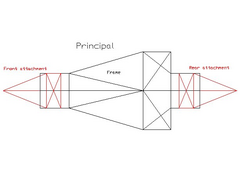 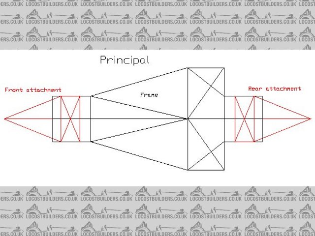
Rescued attachment Principal.jpg
|
|
|
pbura
|
| posted on 22/1/04 at 12:52 PM |
|
|
Peter Ogden's site has Mr. Cymtriks latest writeup on the Locost, a description of the Aussie torsion beam test, Aussie structural mods and lots
of other great stuff:
Clubman Builders Resource
Someone piped up on Locost Theory (I think) recently and said that some FEA work they had done supported Cymtriks' numbers. Maybe one of you
newer posters? If so, cheers to you 
Somewhere I read that a torsional stiffness of twice the car's weight is sufficient. Sort of stands to reason, I guess, if it would take a
shock of 4 Gs one one corner in order to twist the chassis one degree. Would this be the approximate effect?
Pete
|
|
|