A Badger
|
| posted on 3/3/04 at 10:26 PM |

|
|
Another Hazard Cct Diagram
I'm just starting to work my way through the design of my wiring loom with everything in sub-looms with simplified colour coding. Following the
Hazard Circuit problems of the last week I thought I'd start there. so here is the first diagram.
I've used the standard donor switch (Cortina) for simplicity and a simple flasher unit.
Basically there are 2 feeds, 1 that is only active with the ignition and a second that is active all the time. The ignition fed supply only needs to
be sized for half the load (it will only ever power the indicators of one side) so needs to be fused at 5A and the constant feed needs to be fused at
10A.
Both power feeds go through the hazard switch which is also connected into both sides of the indicator circuit.
Hope this helps, I'll try and post the other sub looms soon.
Andrew
 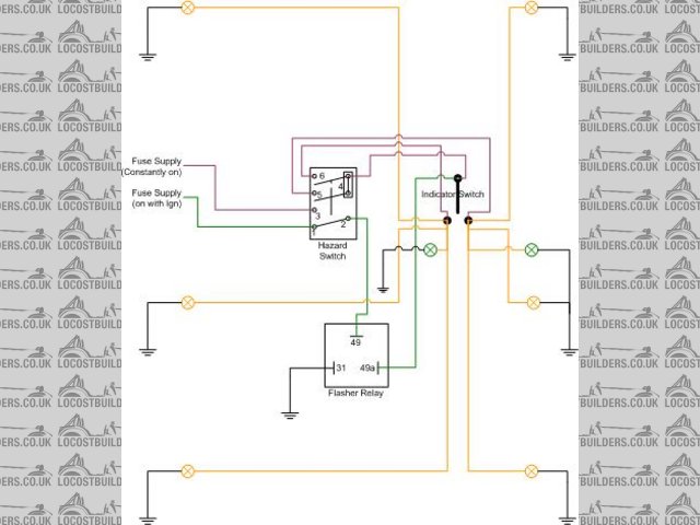
Rescued attachment Indicator and Hazard Circuits.jpg
|
|
|
|
|
Kitlooney1000
|
| posted on 4/3/04 at 03:42 PM |
|
|
wish i had seen that last week, would have saved me tearing my hair out.
|
|
|


