ChrisW
|
| posted on 2/5/12 at 11:03 AM |

|
|
More help needed with my scooter project - chain this time
This scooter project is really making me realise how much more complicated karts are than I expected! 
First off, please don't laugh too much at my crude drawings. I was never very good with CAD, and paint is so much quicker!
So, yesterday I sighted up the chassis with the engine and axle and it strikes me that the engine has to go a long way forward to get the chain at a
sensible angle. Here's what it looks like:
 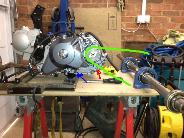
Chain problem
The green obviously being the approximate chain angle, although I've not got a rear sproket yet (or figured out how many teeth it will need so
I'm guessing at the moment).
The problems are that the lower part of the chain will run very close to the casting where the red arrow is. It should be ok as the sproket is proud
of the casing, but there are only a few mm in it. Also it means I can't put the sproket cover on but as it will be covered by bodywork
I'm not sure that matters anyway.
Second problem is that the chassis rail is right in the way of the gear linkage, indicated by the blue arrow so really the engine could do with going
back by at least 50mm, ideally a bit more to keep as much of it 'hidden' under the bodywork as possible, which would compound the problem
of the chain.
Now keep in mind that the axle actually needs to sit the same height as the chassis rail to keep the wheels level, about 45mm down, which is going to
make the chain angle even tighter.
So my initial reaction was to move the engine forward, but that's not ideal for a lot of reasons. Or I could move the engine down, better for
handling etc (not that this thing will handle anyway so that's a bit of a joke!) but then there will be all sorts of problems with the linkages
and it kind of makes the engine vulnerable if there were any bits of debris in the road. Conclusion: ideally the engine will sit at the height in the
photo.
The other solution I can think of is to use some kind of idler on the lower part of the chain, like this:
 
Idler possible solution
(again, sorry for the crap drawing)
That would probably mean I could move the engine back 50-60mm solving the front-end clearance problems and get the major part of the engine under the
bodywork. With any luck, the carb will also end up under the seat where it will get a little protection.
Is an idler pulley something that is 'done' on motorbike/kart/etc chains?
Would something like this do? eBay Item
Keep in mind that the chain will run on this constantly. I'm not sure whether an idler on a bike would normally do this or is just there to
stop the chain going slack on full suspension movements? Will something plastic like that survive constant use?
Any words of encouragement (or otherwise) greatfully received! If there is an obvious gotcha here, please tell me before I plough forward and make a
mess!
Chris
My gaff my rules
|
|
|
|
|
MikeCapon
|
| posted on 2/5/12 at 11:19 AM |
|
|
Can't see the Ebay linky Chris cos I'm not in the UK but if it's any help a lot of off road bikes use a frame mounted idler in
pretty much the same place. The only real consideration is making the mounting strong enough to deal with loads generated on the overrun.
HTH (a bit)
Mike
|
|
|
ChrisW
|
| posted on 2/5/12 at 11:27 AM |
|
|
Hi Mike
Thanks for getting back to me.
It's basically a little plastic idler pulley with a bearing in the middle, probably designed for the same thing as you mention.
On said bikes, does the chain run constantly over the pulley? Or just on the extremes of suspension travel?
Chris
My gaff my rules
|
|
|
Fred W B
|
| posted on 2/5/12 at 11:31 AM |
|
|
Hi Chris
What frame are you using? Can you not modify that the get the bits where you want them? "Z" the whole back of the frame?
If it was not for the casing bit fouling you could put the engine as close to the rear axle as you like. I would not worry about how much
"wrap" you get on the sprockets. I presume you don't want to/can't cut off the casing bit?
First prize is to position the engine offset from the centre line so that the sprockets can run outside of the chassis, which would maybe solve the
gear linkage problem as well?
PS - I guess you are aware you need to make the engine position a little bit adjustable fore and aft to adjust the chain tension? Or if you use an
idiler it can move in and out to do that.
Cheers
Fred W B
[Edited on 2/5/12 by Fred W B]
[Edited on 2/5/12 by Fred W B]
You can do it quickly. You can do it cheap. You can do it right. Pick any two.
|
|
|
ChrisW
|
| posted on 2/5/12 at 11:37 AM |
|
|
quote:
Originally posted by Fred W B
What frame are you using? Can you not modify that the get the bits where you want them? "Z" the whole back of the frame?
If it was not for the casing bit fouling you could put the engine as close to the rear axle as you like. I would not worry about how much
"wrap" you get on the sprockets. I presume you don't want to/can't cut off the casing bit?
First prize is to position the engine offset from the centre line so that the sprockets can run outside of the chassis, which would maybe solve the
gear linkage problem as well?
Hi Fred
Thanks also for replying.
I'm using the stock scooter frame, but I've cut the back part off where the motor would usually go. I'm not sure what you mean by
'Z' the back - can you explain a little?
I'd rather not cut the casing if I can avoid it. Or rather, I'd prefer to do it right at the end when I know this will work. The engine
is brand new, so keeping resale value in it until such a point that I'm confident that I can make this work seems sensible.
Thanks for the point about 'wrap' on the sprockets though. I didn't know that was the correct term for it. Is there any
disadvantage to having a lot of wrap?
Yes, moving the engine so the sprocket is hanging over the side would solve the problems, but it would have to move over a fair way (chassis is ~400mm
wide or so) and then I'd have to hack the bodywork up. The whole point is to make this look as stock as possible.
I'll upload some pics now so you can see where I'm going with this.
Chris
My gaff my rules
|
|
|
HowardB
|
| posted on 2/5/12 at 11:37 AM |
|
|
can you not put the engine "on top of" the axle,... so the drive goes down wards not back?
Just a thought
Howard
Fisher Fury was 2000 Zetec - now a 1600 (it Lives again and goes zoom)
|
|
|
ChrisW
|
| posted on 2/5/12 at 11:39 AM |
|
|
quote:
Originally posted by Fred W B
PS - I guess you are aware you need to make the engine position a little bit adjustable fore and aft to adjust the chain tension? Or if you use an
idiler it can move in and out to do that.
Replying to your edit: Yes, I was planning on having the engine on a skid type arrangement (for want of a better word) that allows it to be slid back
and forward with a threaded rod at the front for tensioning the chain. Obviously some way of tightening it down once it's in position too.
I take Mike's point about forces on overrun, and suggest that I make the idler mounting as strong as possible and not adjustable and keep my
sliding arrangement for chain tensioning.
Chris
My gaff my rules
|
|
|
ChrisW
|
| posted on 2/5/12 at 11:41 AM |
|
|
quote:
Originally posted by HowardB
can you not put the engine "on top of" the axle,... so the drive goes down wards not back?
Just a thought
That would make life easier, yes! However, I'm stuck for vertical height due to the seat. This was the reason I went for a 'pit
bike' style of engine as it has the cylinder slung out in front rather than pointing upwards.
EDIT: And also, as mentioned before, I want to keep this as stock looking as possible. In other words, if I can avoid hacking the bodywork up too
much or having bits of engine sticking out I would consider it a bonus.
Chris
[Edited on 2/5/2012 by ChrisW]
My gaff my rules
|
|
|
Fred W B
|
| posted on 2/5/12 at 11:45 AM |
|
|
quote:
I'm not sure what you mean by 'Z' the back - can you explain a little?
You say the axle wants to be in the same plain as the chassis tubes. Consider mounting the axle bearing mounts upside down, and putting a
"dogleg" or "Z" shaped kink in the side rails to bring them above the axle. So the axle "hangs" under the rear of
the chassis.
_____/ o
I can't put a line above the o (o represents axle) , but you see what I mean?
Fred
You can do it quickly. You can do it cheap. You can do it right. Pick any two.
|
|
|
ChrisW
|
| posted on 2/5/12 at 11:55 AM |
|
|
Got it! Yes, it's possible, but to be honest mounting the axle isn't the biggest issue. It would be creating the 'drop' at
the other end, keeping in mind I want to retain the front half of the chassis with the steering etc on it, and making it strong. Also I'd then
have to have some way of supporting the bodywork. It's do-able, but it would complicate the project a lot!
Another consideration is that I really don't want to drop the ground clearance too much if I can avoid it.
It's something to think about though.... I might change my mind
By the way: I uploaded some photos. Look in my archive under 'scooter project'.
Chris
[Edited on 2/5/2012 by ChrisW]
[Edited on 2/5/2012 by ChrisW]
My gaff my rules
|
|
|
MikeCapon
|
| posted on 2/5/12 at 12:01 PM |
|
|
quote:
Originally posted by ChrisW
Hi Mike
Thanks for getting back to me.
It's basically a little plastic idler pulley with a bearing in the middle, probably designed for the same thing as you mention.
On said bikes, does the chain run constantly over the pulley? Or just on the extremes of suspension travel?
Chris
Yep that's the sort of thing Chris. From (ageing) memory the chain was just about touching at ride height so all the bump movement resulted in
the chain resting on the idler. So the chain was touching the idler for the lower 75%ish of the wheels movement.
|
|
|
ChrisW
|
| posted on 2/5/12 at 12:18 PM |
|
|
quote:
Originally posted by MikeCapon
quote:
Originally posted by ChrisW
Hi Mike
Thanks for getting back to me.
It's basically a little plastic idler pulley with a bearing in the middle, probably designed for the same thing as you mention.
On said bikes, does the chain run constantly over the pulley? Or just on the extremes of suspension travel?
Chris
Yep that's the sort of thing Chris. From (ageing) memory the chain was just about touching at ride height so all the bump movement resulted in
the chain resting on the idler. So the chain was touching the idler for the lower 75%ish of the wheels movement.
Thanks Mike. I wonder if they're strong enough to withstand constant running on the chain. I guess being plastic they're a disposable
item, but it would be nice if it could survive a long weekend of abuse at Le Mans without needing to be changed.
Chris
My gaff my rules
|
|
|
Dangle_kt
|
| posted on 2/5/12 at 12:47 PM |
|
|
I think you are asking that chain roller to do two things - best to follow a tried and tested setup IMO
Bikes use the following setup

chain roller close to the front sprocket and a rear chain guide to make sure it stays aligned even when a little slack (dont forget if you have the
engine on runner system there is the potential it might twist slightly, putting sideways load on the chain (without the rear chain guide you could be
looking at a plastic smashing derailment - both can be bought really cheaply here
http://www.pitbikeparts.co.uk/chains-guides-chain-adjusters-guides-tensioiners-rollers-c-33_60.html
the above setup means you dont have to run the chain supertight, this will reduce the load on the chain roller significantly
[Edited on 2/5/12 by Dangle_kt]
|
|
|
ChrisW
|
| posted on 2/5/12 at 12:49 PM |
|
|
Hi
I don't think I'll have the space for a rear chain guide!
My point, I guess, is that my scooter doesn't have any suspension, so the chain will run on the roller all the time. Are such plastic rollers
strong enough to hold up to this?
Chris
My gaff my rules
|
|
|
Dangle_kt
|
| posted on 2/5/12 at 01:22 PM |
|
|
as i mentioned, it depends on the tension of the chain, and if its supported on both side - normally its only supported on one side, but running the
chain too right can bend the "bolt" it runs on (this has happened to me once when I change rear sprockets and didn't adjust the
chain)
Also the chain roller in the middle is unlikely to stop a derailment -but I guess it depends what you want the roller to to - (or just fit two if
space is tight? one near the engine, one near the axle?) - also it doesn't need to be a bought chain guide, two bits of round either side of the
sprocket would prevent a derailment, but as you were looking for off the shelf stuff, thats what I linked too.
|
|
|
ChrisW
|
| posted on 2/5/12 at 01:49 PM |
|
|
On further research, I think I might be grossly overestimating the diameter of the rear sprocket.
I'm told that a pit bike would typically have a 14-15 tooth front sprocket and a 39-41 tooth rear. That gives a ratio of 2.6-2.9:1. A typical
pike bike has a 450mm diameter rear wheel, so 1.4m circumference.
The scooter wheels are 330mm diameter, so roughly 1.05m circumference.
So, if my maths is right, I need roughly a 2:1 ratio front to back to achieve the same performance as a bike.
It seems the biggest front sprocket I can get is 18 tooth, so rear needs to be 36 teeth.
So something like this: eBay Item
Going on the picture, I guestimate that being 120mm diameter, which is a lot less than I was expecting.
I think another sight-up is in order to see whether, with a smaller sprocket, I'm creating more problems for myself.
Chris
My gaff my rules
|
|
|
Dangle_kt
|
| posted on 2/5/12 at 02:06 PM |
|
|
if you find you need any pit bike bits or pieces your struggling to get cheap give me a shout, I have loads of old bits knocking round.
|
|
|
ChrisW
|
| posted on 2/5/12 at 03:06 PM |
|
|
quote:
Originally posted by Dangle_kt
if you find you need any pit bike bits or pieces your struggling to get cheap give me a shout, I have loads of old bits knocking round.
Thanks, I may well do that!
Chris
My gaff my rules
|
|
|
Fred W B
|
| posted on 2/5/12 at 05:55 PM |
|
|
Having now looked at the pictures, it makes more sense. If you are looking to get the motor as low as possible I would reposition that cross member
under the engine and hang the motor so that the lowest point is flush with the bottom of the frame. A sheet of steel under it (welded to the frame) as
a bash plate will protect it if necessary.
I have to ask, you are going to replace the seat with a tin top race car style one?
Re the gearing, I don"t know what RPM the motor turns, but at 5000 rpm/2.1ratio*1.037 circ = 2469 m/s, which equals = 148 km/hour, or 90 mph, so
you may want to rethink the ratios?
Cheers
Fred W B
[Edited on 2/5/12 by Fred W B]
You can do it quickly. You can do it cheap. You can do it right. Pick any two.
|
|
|
Dangle_kt
|
| posted on 2/5/12 at 07:08 PM |
|
|
quote:
Originally posted by Fred W B
A sheet of steel under it (welded to the frame) as a bash plate will protect it if necessary.
[Edited on 2/5/12 by Fred W B]
if its easier?
http://www.pitbikeparts.co.uk/advanced_search_result.php?inc_subcat=1&search_in_description=0&keywords=bash&osCsid=i6pnibjg678guatkkfh7gnn
mv7
pit bike engines run out of puff at approx 10k rpm, unless they have some head work (which is really easy BTW) high lift cam etc.
if that helps?
|
|
|
Fred W B
|
| posted on 2/5/12 at 08:16 PM |
|
|
but hang on, I haven't considered any internal gerabox reduction from crank speed to output shaft speed
Cheers
Fred W B
You can do it quickly. You can do it cheap. You can do it right. Pick any two.
|
|
|
stevebubs
|
| posted on 2/5/12 at 08:38 PM |
|
|
Am I missing something, or could you not just remove the bit of casting that is causing the clearance issue?
|
|
|
owelly
|
| posted on 3/5/12 at 01:03 PM |
|
|
Erm.....
http://item.mobileweb.ebay.co.uk/viewitem?itemId=140743412499
http://www.ppcmag.co.uk
|
|
|
ChrisW
|
| posted on 3/5/12 at 01:13 PM |
|
|
Interesting find. I'd have had a bid on that if I'd have known!
eBay Item
^^ link for those of us on a PC. Owelly's link goes to mobile eBay.
Chris
My gaff my rules
|
|
|
ChrisW
|
| posted on 6/5/12 at 11:12 AM |
|
|
quote:
Originally posted by Fred W B
Re the gearing, I don"t know what RPM the motor turns, but at 5000 rpm/2.1ratio*1.037 circ = 2469 m/s, which equals = 148 km/hour, or 90 mph, so
you may want to rethink the ratios?
Just to update on this, as I've now got the engine I'm able to answer properly. I took the crank cover off last night so I could turn the
engine over and work out the ratios.
1st gear = 10:1
4th gear = 3.5:1
(both approximate, but good enough for this calculation).
My current engine sprocket has 15 teeth. Rolling circumference of the wheels is 105cm. I'm assuming that max rpm is 10k, as per
dangle_kt's post.
So, in top gear, 10k rpm of the engine is 2850rpm of the sprocket. Going on 32-tooth rear sprocket (closest available to 2:1 ratio) that gives
1335rpm of the rear axle = roughly 84kph flat out in top gear (52mph)
I think that's the right ball park to get started as aerodynamics and weight will probably come into play well before then, and anyway it will
probably be completely unstable at those speeds, but I welcome your opinions!
Chris
My gaff my rules
|
|
|