jamie1107
|
| posted on 8/8/08 at 11:11 AM |

|
|
ROCKER ARM FRONT SUSPENSION
Hi does anyone have any info on the locost book chassis with the push rod / pull rod suspension
i have seen a few designs at various shows using 3 coil overs for the front all inboard mounted
im sure there are loads of chassis you can buy but thats not in the spirit of locost lol
so i wanted to have a go at modifying the chassis
i realise there is alot of room for error but im sure with some research and help from the forum i can work something out
|
|
|
|
|
mark chandler
|
| posted on 8/8/08 at 12:10 PM |
|
|
I do not think you will find a Locost solution that's docmented as its all home brew for inboard.
All you can do is have a google and copy the solution you prefer.
So rocker which loads the top ball joint (they are transit TRE's so not designed for this load) or my preference would b rod and bell crank but
this takes a lot more thought to achieve good results but loads the bottom ball joint.
Just have a mock up, when it feels correct weld it up and see how you get on.
Regards Mark
|
|
|
meany
|
| posted on 8/8/08 at 01:19 PM |
|
|
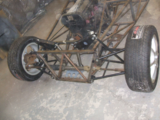
the one im doing at the moment has inboard suspension (as bought off " TPG" . .
im not too sure on the ratio, about 2.6:1 i think, to be honest im not too sure about it...whats anyone else's thoughts?
Description
[Edited on 8/8/08 by meany]
|
|
|
mr henderson
|
| posted on 8/8/08 at 02:33 PM |
|
|
quote:
Originally posted by meany
im not too sure on the ratio, about 2.6:1 i think, to be honest im not too sure about it...whats anyone else's thoughts?
Now would be the time to measure it, before you put springs on. I presume the ratio referred to is total wheel movement to shock absorber movement?
Might be interesting to make a number of intermediate measurements, then plot the results on a graph, which will result in a curve
John
|
|
|
meany
|
| posted on 8/8/08 at 04:03 PM |
|
|
you are correct in your assumption.
i'll do the graph thingy like you say.
|
|
|
Rod Ends
|
 posted on 8/8/08 at 04:14 PM posted on 8/8/08 at 04:14 PM |
|
|
Freestyle do a bolt-on modification for Caterhams to give inboard suspension.
|
|
|
Cheffy
|
| posted on 8/8/08 at 07:28 PM |
|
|
Hi James,
I'm going inboard on my V8. Click on the link at the bottom of this post and go to my website for loads of pics.
I'm certainly no expert and am learning as I go. I more or less copied Alan B's initial design (with his permission ) and adapted it to
my situation.
Mark is quite right. The transit TRE's are not up to the job. Bearing in mind that in my design the load is taken on the top joint the transit
TRE's are not designed to take that kind of load in shear. You'll see on my website that I've changed from transit TRE's to
Saab top ball joints - which are designed to take the load in shear. (Just realised I haven't updated my website for a while. The new top outer
wishbones are now complete and fitted - I'll get the website updated shortly!)
Hope that helps some,
Cheers,
Mart.
Farts are like Rock'n'Roll. You love your own but you hate everybody else's. Lemmy, Motorhead.
|
|
|
Cobra289
|
| posted on 8/8/08 at 08:14 PM |
|
|
Well Jamie 1107,
It is not so simple as it likes. My experiences are:
I have done a rocker design taking in account the dynamics and not only the kinematics [movements] to determine the initial ratio of the rocker.
I though that I was in the right direction but when I did present it to my suspension advisor, his comments where hard.
He just say "Forget about it" a car that will drive on the road needs at least a drop of 75 mm before the rocker meets the critical point
in his rotation. [90° in relation to the push-rod]
After a fast "Lagrangian's analysis" we found that the ratio was OK but that angular variations where huge and therefore we
will introduce a lot of problems.
The next observation from him was:
Don't use a rocker type suspension in a car with a roll ratio of 1° of more, it is just bellow that figure when the advance of a rocker will be
exponential.
It is just interesting for cars with a very low suspension travel, we are talking here in millimeters instead of centimeters.
A rocker is a nice design to adjust the rigidity of the suspension without the needs of changing the spring rigidity, but there are more solutions for
that.
I hope that this opinion help you, but please never forget that is just an opinion.
Regards,
Cobra289
https://forocoches.com/foro/showthread.php?t=1699619
|
|
|
jamie1107
|
| posted on 9/8/08 at 12:27 PM |
|
|
thats given me allot to think about the car is a locost based track car i want to develop looking at the freestyle motorsport site (thanks for that
link )they claim it gives a 1to 1 ratio of wheel movement to damper travel which if the info i have been reading is correct can only help things
i realise it probably wont make that much difference on the road but for a track inspired car it could prove to be quite handy
i have to say i do like the design you have there in the pic meany are those sierra hubs your using
what hubs do you use in your system cheffy
im assuming you would use a book wishbone and just pick up the rocker arm with a rod end onto the lower shock mount om i right
i will have to read up a bit more on suspension technology as at present im undure of the rocker ratio s and the best mounting points etc but im sure
it can alll be learnt
on a last note has anyone seen the systems which use 3 coil overs im wondering what the purpose of the third shock is as im not sure if its there as a
ajustable arb or to ballance the left and right shocks out any thoughts guys ?
|
|
|
meany
|
| posted on 9/8/08 at 02:14 PM |
|
|
i have been and measured mine this morning and produced a graph.
let me know your thoughts please.Image deleted by owner
|
|
|
mr henderson
|
| posted on 9/8/08 at 02:30 PM |
|
|
That's an impressive piece of work. Unfortunately atlthough I have some understanding of the physics involved, neither my maths nor my knowledge
of which shock absorbers are best suited to this apllication are up to my producing a useful comment.
I'll be interested to see waht others have to say, though. The shock travel does look quite short, but then it will be in most LSIS set-ups, if
not nearly all.
John
[Edited on 9/8/08 by mr henderson]
|
|
|
meany
|
| posted on 9/8/08 at 02:32 PM |
|
|
thanks for having a look.
i can always ditch it but that means remaking the top wishbones to allow space for the shocks.
|
|
|
britishtrident
|
| posted on 9/8/08 at 04:01 PM |
|
|
The three things to watch are:
(1) that the rocker pivot fulcrums on the chassis are properly triangulated and mounted in double shear. --- they take at least twice the load of
conventional spring mounts.
(2) The spring/damper unit mounts on the chassis are properly triangulated and mounted in double shear.
(3) the rockers themselves are stiff enough so as not act as undamped leaf springs.
90% of attempts at rocker arm suspension on Locost based chassis don't come anywhere near meeting the first two criteria.
[Edited on 9/8/08 by britishtrident]
|
|
|
Volvorsport
|
| posted on 9/8/08 at 04:34 PM |
|
|
http://homepage.ntlworld.com/david.slater133/davesshop3.JPG
my version.
the dampers could do with spacing out at the bottom, i might get some understeer then !!
www.dbsmotorsport.co.uk
getting dirty under a bus
|
|
|
britishtrident
|
| posted on 9/8/08 at 06:39 PM |
|
|
quote:
Originally posted by Volvorsport
http://homepage.ntlworld.com/david.slater133/davesshop3.JPG
my version.
the dampers could do with spacing out at the bottom, i might get some understeer then !!
Like the rocker & its' fulcrum mounting --- cool
[I] What use our work, Bennet, if we cannot care for those we love? .
― From BBC TV/Amazon's Ripper Street.
[/I]
|
|
|
pbura
|
| posted on 10/8/08 at 12:32 PM |
|
|
Meany, you have a motion ratio, or total leverage, of 4:1 throughout most of the relevant range, which is a bit tall. It means that your spring rate
must be 16 times your desired wheel rate. A typical wheel rate is 100 lbs/inch, so you can see where this is going.
Besides the rocker ratio, you get additional leverage from the pushrod angle, and also from the placement of the pushrod with respect to the center of
the tire patch though this is not a huge factor. Essentially, your problem is the rocker ratio.
Let's say your goal is a wheel rate of 100# (I'm not saying this is correct, but just an example) with a 550# bike shock having a stroke
of 2". The ratio of spring rate to wheel rate would be 5.5:1, the square root of which would be the motion ratio of 2.35:1. We already know
that leverage due to factors other than the rocker is 1.64:1 (or 4 divided by 2.44). This leaves a desired rocker ratio of 1.43:1 (2.35 divided by
1.64).
In this example, you would have wheel travel of 4.7 inches (2" shock stroke X 2.35).
There may be a little more putzing around because a different rocker will probably change the pushrod angle, but you get the idea.
Usually, the rocker is the very last thing to buy or make for an inboard system. If you can, make one with alternate mounting holes so you can have
'street' and 'race' settings, which would be pretty cool.
Best of luck!
Pete
|
|
|
Syd Bridge
|
| posted on 10/8/08 at 03:34 PM |
|
|
Why would anyone want to add all that extra weight to what is meant to be a light and nimble car?
Then to top it all, give themselves the agro of everchanging leverage ratios and spring rates.
Other than, 'because it can be done', there is no plausible reason on this earth to put any type of rocker suspension on the front (or
rear) of a 7 type car.
Keep it simple, sir. 
Cheers,
Syd.
|
|
|
pbura
|
| posted on 10/8/08 at 07:46 PM |
|
|
http://motors.shop.ebay.com/_Motorcycle-Parts-Accessories__r6-shock_W0QQMake247a0eZYamaha9d693cb5QQ_nkwZr6Q20shockQQ_catZ6000QQ_fxdZ1
Pete
|
|
|
Cobra289
|
| posted on 10/8/08 at 10:01 PM |
|
|
I have some points to mention for the enthusiasm builders-designers.
- Watch the ideal travel [range]of the damper and work only on that area.
- The angle between the rocker and the damper should be far less than 90° [sorry I don't know the word for it] (perhaps "Acute"
angle?)
- When you introduce a ratio be careful with the introduced working speed at the damper. Dampers don't like to work at extreme speed and they
are not made for that extra speed.
The third coil-over is not a direct member of the front suspension it is more to control the pitch. [Longitudinal angle]
Regards,
Cobra289
[Edited on 10/8/08 by Cobra289]
[Edited on 10/8/08 by Cobra289]
https://forocoches.com/foro/showthread.php?t=1699619
|
|
|
Liam
|
| posted on 11/8/08 at 10:43 PM |
|
|
My version in me photo archive...
Did it mainly cos (a) there's no cheap load bearing lower ball joint to fit the 4x4 upright pinch bolt, (b) for the adjustability it allows. I
then did it on the rear pretty much cos I was doing it on the front
My setup uses 350lb on the front and 400lb on the rear. Wheel rate is adjustable from 80-120 cpm front, and 85-130 rear (5 steps both ends).
IMHO, for a road/track car, the added complexity of a push rod, bell crank design offers no appreciable benefit over this simple rocker design for a
lot of extra hassle/pivots to locate accurately/parts to wear etc.
Liam
|
|
|
stevebubs
|
| posted on 12/8/08 at 12:44 AM |
|
|
quote:
Originally posted by Liam
My version in me photo archive...
Did it mainly cos (a) there's no cheap load bearing lower ball joint to fit the 4x4 upright pinch bolt, (b) for the adjustability it allows. I
then did it on the rear pretty much cos I was doing it on the front
My setup uses 350lb on the front and 400lb on the rear. Wheel rate is adjustable from 80-120 cpm front, and 85-130 rear (5 steps both ends).
IMHO, for a road/track car, the added complexity of a push rod, bell crank design offers no appreciable benefit over this simple rocker design for a
lot of extra hassle/pivots to locate accurately/parts to wear etc.
Liam
Also look at Jeremy Phillips front rockers... as fitted to
Striker
Fury
Phoenix
Stylus
etc
Same principles....
|
|
|
kb58
|
| posted on 15/8/08 at 01:24 AM |
|
|
I tried like crazy to avoid rocker arms, but for my build, the rear suspension was such that it was the only decent solution.
Mid-engine Locost - http://www.midlana.com
And the book - http://www.lulu.com/shop/kurt-bilinski/midlana/paperback/product-21330662.html
Kimini - a tube-frame, carbon shell, Honda Prelude VTEC mid-engine Mini: http://www.kimini.com
And its book -
http://www.lulu.com/shop/kurt-bilinski/kimini-how-to-design-and-build-a-mid-engine-sports-car-from-scratch/paperback/product-4858803.html
|
|
|
jamie1107
|
| posted on 13/9/08 at 12:37 PM |
|
|
thans for all the info guys can anyone recomend any good books or computor modeling programs for designing this up or even better and i know im being
a bit cheaky but would anyone have any drawings and measurements of a system thay have used on their locost with sucess
thanks
guys
|
|
|
Theshed
|
| posted on 13/9/08 at 06:27 PM |
|
|
I have used susprog which you can download online. It is easy to use but is about £100. You can calculate your suspension mountings to within a thou
or two provided you know what you want in the first place!
|
|
|
meany
|
| posted on 17/9/08 at 02:02 PM |
|
|
quote:
Originally posted by pbura
Meany, you have a motion ratio, or total leverage, of 4:1 throughout most of the relevant range, which is a bit tall. It means that your spring rate
must be 16 times your desired wheel rate. A typical wheel rate is 100 lbs/inch, so you can see where this is going.
Besides the rocker ratio, you get additional leverage from the pushrod angle, and also from the placement of the pushrod with respect to the center of
the tire patch though this is not a huge factor. Essentially, your problem is the rocker ratio.
Let's say your goal is a wheel rate of 100# (I'm not saying this is correct, but just an example) with a 550# bike shock having a stroke
of 2". The ratio of spring rate to wheel rate would be 5.5:1, the square root of which would be the motion ratio of 2.35:1. We already know
that leverage due to factors other than the rocker is 1.64:1 (or 4 divided by 2.44). This leaves a desired rocker ratio of 1.43:1 (2.35 divided by
1.64).
In this example, you would have wheel travel of 4.7 inches (2" shock stroke X 2.35).
There may be a little more putzing around because a different rocker will probably change the pushrod angle, but you get the idea.
Usually, the rocker is the very last thing to buy or make for an inboard system. If you can, make one with alternate mounting holes so you can have
'street' and 'race' settings, which would be pretty cool.
Best of luck!
thanks for your input, i'll have to read a few times for it to sink in....lol.
Rob.
|
|
|