Davegtst
|
| posted on 3/4/15 at 04:28 PM |

|
|
Any electrical geniuses about? reducing voltage
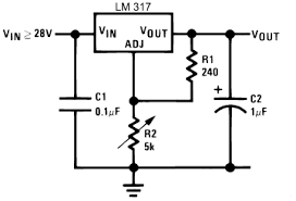
I'm trying to convert 12v from an ignition live down to around 3.5v which will be an input into my ecu. I've been looking up how to do it
and have come across this circuit diagram that uses an LM317 and a potentiometer. While I can make this circuit easily enough can I not just use a
potentiometer in series to reduce the voltage?
|
|
|
|
|
gremlin1234
|
| posted on 3/4/15 at 04:43 PM |
|
|
a stable voltage using the circuit you have detailed is much, much better than just a series resistor/potentiometer , though I would have thought
using a simpler 7805 (5V max 1A) would be the way to go.
ps, don't forget a heatsink for the regulator
[Edited on 3/4/15 by gremlin1234]
|
|
|
Davegtst
|
| posted on 3/4/15 at 05:03 PM |
|
|
Ok, thanks for the help. I assume the only difference is the 7805 is a maximum 5v so it won't go above and damage anything?
|
|
|
gremlin1234
|
| posted on 3/4/15 at 06:26 PM |
|
|
7805 is a fixed 5V regulator, so requires less external components than a 317 (variable voltage)
common 7805 circuits deliver a max current of 1Amp.
|
|
|
avagolen
|
| posted on 3/4/15 at 06:47 PM |
|
|
If you really do require 3.5 volts, I would stick with the 317.
If 5 volts is ok, go with the 7805.
HTH
Len.
The Answer for everything, but never the last word....
|
|
|
Davegtst
|
| posted on 3/4/15 at 07:07 PM |
|
|
Yes definitely need around 3.5v. I need to stimulate about 80 percent on the tps to fool an ecu into open loop.
|
|
|
Slimy38
|
| posted on 3/4/15 at 07:11 PM |
|
|
Using a potentiometer will simply split the input voltage, and with an average car circuit going between 11 and 15 volts there would be a
corresponding change in output (probably not good for an ECU). The LM317 puts out a fixed voltage as long as the input voltage stays within the
operating range.
|
|
|
gremlin1234
|
| posted on 3/4/15 at 07:25 PM |
|
|
quote:
Originally posted by Davegtst
Yes definitely need around 3.5v. I need to stimulate about 80 percent on the tps to fool an ecu into open loop.
ah, if its just a voltage to
an input, then 317 is the way to go, you can get very low power versions on these, and you won't need a heatsink.
the 317 in a t092 package is probably best for this.
http://www.sky-macau.com/Products/Voltage-Regulator-C92/LM317-LM317LZ-Low-Power-Positive-Adjustable-Voltage-Regulator-12V-to-37V-01A-100mA-TO-92-P1012
675676.html
but if the original tps was just a potentiometer, then one will do for that. (all the smoothing will have been done in the ecu, supplying the pot)
|
|
|
Marcos Controls
|
| posted on 3/4/15 at 07:36 PM |
|
|
Hi, Is there not already a 5V supply coming from the ECU that supplies the TPS? I did something similar and just made a voltage divider using 2
resistors between the pins on the ECU.
Cheers
Marc
|
NOTE:This user is registered as a LocostBuilders trader and may offer commercial services to other users
|
ChrisW
|
| posted on 3/4/15 at 08:01 PM |
|
|
If it's a 5v feed to the TPS and you just want to fool the ECU (not actually draw power to run something) just use two resistors.
1.8k (1800 ohms)
820 ohms
Wire them like this:
5v ----[ 820 ] -----*------- [ 1.8k ]----- 0v
Connect the TPS input to the ECU to where the star is.
You should see 3.43v which should be close enough?
Cheers, Chris
My gaff my rules
|
|
|
Davegtst
|
| posted on 3/4/15 at 08:20 PM |
|
|
Trouble is its very sensitive to the voltage. I haven't checked exactly what voltage I need yet but 4v is too much and 3v won't put the
car in open loop. I need the potentiometer to set the voltage just right.
|
|
|
Marcos Controls
|
| posted on 3/4/15 at 08:23 PM |
|
|
quote:
If it's a 5v feed to the TPS and you just want to fool the ECU (not actually draw power to run something) just use two resistors.
1.8k (1800 ohms)
820 ohms
Wire them like this:
5v ----[ 820 ] -----*------- [ 1.8k ]----- 0v
Connect the TPS input to the ECU to where the star is.
You should see 3.43v which should be close enough?
Cheers, Chris
I did exactly as Chris has described, the values aren't critical as long as the ratio stays the same, 1k and 2k2 which are more commonly
available would probably do the trick.
also, most ecus use 2 different TPS inputs. one reading 0-5V while the other mirrors it reading in reverse from 5-0V. Cross-checking I believe
it's called. It's to prevent you losing throttle control if one of the two potentiometers fail, but I'm no expert and please someone
correct me if I'm mistaken.
Cheers
Marc
|
NOTE:This user is registered as a LocostBuilders trader and may offer commercial services to other users
|
Davegtst
|
| posted on 3/4/15 at 08:43 PM |
|
|
This had definitely only got one 0 to 5v input. It also starts at 12 percent and stops at around 80 percent. If the ecu sees anything above 80 or
below 12 percent it brings on the check engine light.
|
|
|
ChrisW
|
| posted on 3/4/15 at 10:07 PM |
|
|
quote:
Originally posted by Marcos Controls
also, most ecus use 2 different TPS inputs. one reading 0-5V while the other mirrors it reading in reverse from 5-0V. Cross-checking I believe
it's called. It's to prevent you losing throttle control if one of the two potentiometers fail, but I'm no expert and please someone
correct me if I'm mistaken.
That's usually on 'drive by wire' systems, ie the potentiometer on the pedal then controls the throttle position by a motor. I had
assumed the OP was using a conventional cable throttle with TPS connected to that just feeding the ECU but I may be wrong!
If you need precise control just use a potentiometer (preset probably best) in place of the two resistors.
Chris
My gaff my rules
|
|
|
coyoteboy
|
| posted on 3/4/15 at 11:01 PM |
|
|
Just a quick point, really you should have a lot more supporting circuitry not just the 7805 in a harsh environment like a car electrical system.not
unusual to see spikes much higher than the 7805 Max input voltage for example, plus you want protection from a failed 7805 taking out other systems.
If its going into a known load and fed from a known preconditioned power source you may be OK, but then you may be OK with just a pot too in that
case.
|
|
|
Davegtst
|
| posted on 4/4/15 at 06:32 PM |
|
|
I made it today using an lm317. It works perfectly, thanks for all your help.
|
|
|