big-vee-twin
|
| posted on 15/10/11 at 07:56 AM |

|
|
Just Imported a Megasquirt MS2V3
Morning all, just imported a Megasquirt kit from DIYAutotune, going to start soldering up this afternoon. Initially I was going to buy an assembled
kit but as I used to work as an electrician repairing control panels soldering 6 hours out of every 8 every day for 8 years (20 years ago) I would
revive the old skills and have ago at putting one together.
This is what arrived, I will keep taking some photographs through the assembly to keep a diary and report back how hard difficult it is if, anyone is
interested?
[img]
 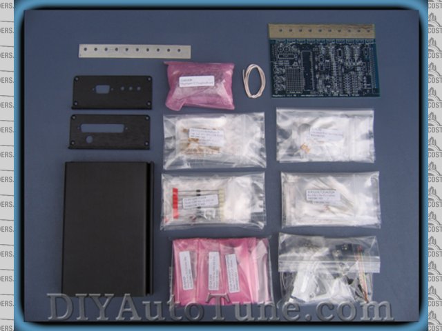
Megasquirt Kit
[/img]
Oh, I forgot to mention they are running a promotion to offer 12% discount, but to get this they want to drive up their 'Likes' on
Facebook to 6000, so have a look on their page and press like and in no time the discount will be available for those who are planning a purchase.
[Edited on 15/10/11 by big-vee-twin]
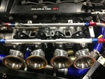
Duratec Engine is fitted, MS2 Extra V3 is assembled and tested, engine running, car now built. IVA passed 26/02/2016
http://www.triangleltd.com
|
|
|
|
|
monck
|
| posted on 15/10/11 at 08:29 AM |
|
|
i would be intrested to hear how difficult it is as i was thiking of a kit also
Good luck
Ryan
|
|
|
lotusmadandy
|
| posted on 15/10/11 at 08:51 AM |
|
|
I bought one of the v3 self assembly kits.
Tbh it was a doddle to put together,i just
prined off the build manual and followed it
to the letter.It helps if you have a stim
for testing as well.You will also need a fine
tip in your soldering iron.
Andy
|
|
|
Snuggs
|
| posted on 15/10/11 at 08:57 AM |
|
|
Most of the soldering is straight forward however there are a few small transistors that the pads are extremely close together and it is easy
to get a solder bridge.
Do ALL the tests that are in the assembly instructions when you are told to do them.
Take your time and you should be OK.
----------------------------------------------------------------------------------------------------
http://www.topcashback.co.uk/ref/snuggstcb
Spider pig, spider pig, does whatever a spider pig does.
I doubt therefore I may be.
Luposlipophobia : Fear of being chased by wolves around a freshly waxed kitchen floor, while wearing only socks on your feet.
My mind not only wanders, sometimes it leaves completely!
http://www.venganza.org
http://www.jesusandmo.net/
http://www.snuggs.co.uk
|
|
|
RK
|
| posted on 15/10/11 at 03:21 PM |
|
|
I had a bad ECU, decided to change it, thought about this, realised I couldn't solder that well (and I've done HUNDREDS of wires in my
car), there weren't a lot in engines like mine (CA18DET) and bought an AEM for about 5 or 6 times the price. I want to see this work, so keep us
informed would you?
BTW, I bought another small kit at the electronics store, for practice, which I tried to make work, but couldn't. My car wires are solid however
(they all passed the pull test), but obviously larger, leaving a lot of room for error.
|
|
|
big-vee-twin
|
| posted on 15/10/11 at 04:05 PM |
|
|
Ok, here's the fruits of my Labour today- built the stimulator.
You put it together in no particular order just put the numbered components in the numbered holes -bit like painting by numbers really.
The transistor pads are very close together as previously said but managed to get them done with a little patience, everything else was very easy.
I had treated myself to a new soldering station with anti static connection. I connected this to an anti static soldering mat and connected myself to
it by a wristband. Here's a pic took about three hours to do.
If you notice I haven't connected one of the resistor legs yet-I'm going to use this LED which is designed for the Idle valve, which I
haven't got, to monitor a second coil output as I am planning to mod the MS to waisted spark without using EDIS
[img]
 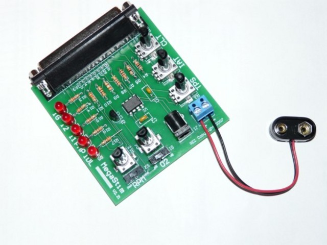
MS Stimulator built
[/img]
Duratec Engine is fitted, MS2 Extra V3 is assembled and tested, engine running, car now built. IVA passed 26/02/2016
http://www.triangleltd.com
|
|
|
big-vee-twin
|
| posted on 16/10/11 at 05:08 PM |
|
|
Here's some more progress pics, the stage 1 build of the 5 Volt regulator is now complete and tested out ok.

[img]
 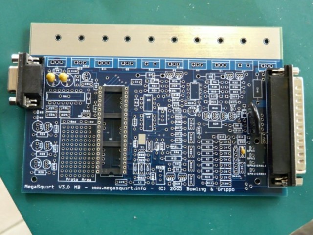
Stage 1 MS build
[/img]
[img]
 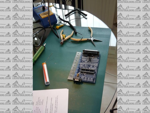
Kitchen table
[/img]
[img]
 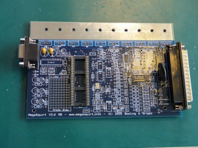
Megasquirt build stage 1
[/img]
All very straightforward so far, just following the instructions and using the layout diagram to locate component positions.
Duratec Engine is fitted, MS2 Extra V3 is assembled and tested, engine running, car now built. IVA passed 26/02/2016
http://www.triangleltd.com
|
|
|