needforspeed
|
| posted on 17/3/13 at 10:20 AM |

|
|
load cell / strain guage wiring
i have this load cell apparently push and pull that im going to use for my flatshifter kit, but how do you wire them up? checked resistance pushing
and upulling but nothing changes?? is it just a pull or push type and needs power??

|
|
|
|
|
rf900rush
|
| posted on 17/3/13 at 10:51 AM |
|
|
High.
The ones I have used are wired in a Bridge.
2 wires went to 0 volts and + 5 volts.
the other 2 were the differential outputs. One went positive the other went negative.
If you can fine a part number for it, this may help find some data on it.
The Output voltage is generally very small. millivolts per Volt at full load.
Something like 1millvolt when powered by 5 volts
It is very likely you will need some electronics.
Diagram example.
 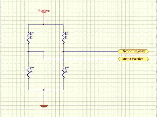
Bridge
This May help.
LINK
I can only see 3 wires. is this correct?
If so I is only a half bridge, or nothing Like I have used.
[Edited on 17/3/13 by rf900rush]
|
|
|
needforspeed
|
| posted on 17/3/13 at 11:03 AM |
|
|
brill thanks alot! il have to bite the bullet and buy one from flatshifter if its only a 1 way :-(
|
|
|
rf900rush
|
| posted on 17/3/13 at 07:15 PM |
|
|
A half bridge may still be push pull. The full bridge types are better for electrical noise.
The better ones use 4 strain gauges.
You could measure the resistance between the wires.
If 2 wires show double the others the you could try applying 5 volts across the two with the highest resistance.
The use a volt meter to measure the remaining wire, which may change a little with force.
|
|
|
needforspeed
|
| posted on 17/3/13 at 07:38 PM |
|
|
That's it there's no resistance between any of the wires
|
|
|


