907
|
| posted on 16/8/05 at 08:50 PM |

|
|
Voltage reducer ?
Help needed again lads.
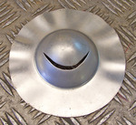
Is this oblong thingy, the gadget that I need for the fuel gauge and temp gauge?
If so, is it wired before the gauges,
i.e. pos to either I or B, then from I or B to gauge, then gauge to sender (earth).
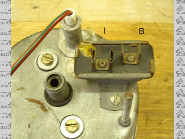
What's "I" (female) & "B" (male) stand for ?
Sorry about this but I am the original electrical dipstick.
Many thanks,
Paul G
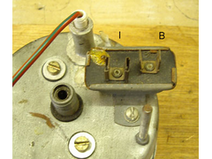 
Rescued attachment wiring2s.jpg
|
|
|
|
|
johnjulie
|
| posted on 16/8/05 at 09:54 PM |
|
|
THe Voltage Stabiliser body must be connected to earth, usually by the bracket.
The "B" terminal is the live feed from the ignition switch.
The "I" terminal goes to the Instuments, ie Fuel and Temp gauges.
The other side of the gauges are via their respective sender units to earth.
Cheers John
JFDI
"Just F*****G Do It"
|
|
|
907
|
| posted on 16/8/05 at 11:45 PM |
|
|
"I" for Instruments.
Why didn't I think of that ?
Cheers John
Paul G
|
|
|
NS Dev
|
| posted on 17/8/05 at 08:31 AM |
|
|
Those crappy oblong thingies pack in all the time and send the gauges all over the place!
If you have a bored evening and the inclination, it's worth making one of these, we use them on Opel Mantas in the club all the time to replace
duff mechanical regulators. I know nothing about electronics and still managed with no trouble!
DIY Voltage Regulator
|
|
|
MikeRJ
|
| posted on 17/8/05 at 12:07 PM |
|
|
quote:
Originally posted by NS Dev
Those crappy oblong thingies pack in all the time and send the gauges all over the place!
If you have a bored evening and the inclination, it's worth making one of these, we use them on Opel Mantas in the club all the time to replace
duff mechanical regulators. I know nothing about electronics and still managed with no trouble!
DIY Voltage Regulator
Note that it is extremely advisable to use input decoupling caps with three terminal regulators, especialy if they have any length of wiring between
the voltage source and input pins. Failure to do so can cause them to oscillate quite strongly. This wouldn't have any noticeable affect on
most instruments, but would make the regulator dissipate excessive heat and could cause interfereance with radios etc. A 0.1uF ceramic cap connected
as close as possible to the input and ground pins of the regulator should suffice.
Also the 7810 is not overly suitable for this application, it has a drop out voltage of 3 volts, so it will only just be in regulation with the
typical 13.8 volts with a running engine. The LM317 is better with a typical drop out voltage of between 1.5 to 2 volts.
|
|
|
NS Dev
|
| posted on 17/8/05 at 10:08 PM |
|
|
being an electrical dumbass (well, a bit anyway!).....do the capacitors just leak any "return" oscillation to ground, thus damping it
out?
Hadn't thought of that if that is the case, worth remebering for my next one!
|
|
|
MikeRJ
|
| posted on 18/8/05 at 12:28 PM |
|
|
quote:
Originally posted by NS Dev
being an electrical dumbass (well, a bit anyway!).....do the capacitors just leak any "return" oscillation to ground, thus damping it
out?
The reason why regulators can oscillate is a little complex, but essentialy the length of wire from the voltage source to the input can have
significant inductance. Inductance tries to prevent changes in current, e.g. if you reduce the current through an inductor, the voltage rises in
order to try and maintain the current (which is how an igntion coil works).
If the regulator tries to take more current, the inductance causes it's input voltage to drop, likewise if it takes less current the input
voltage will rise, so the regulator is essentialy fighting the action of the input inductance, causing the oscillation. A capacitors role in life is
to resist changes in voltage, so a capacitor on the input essentialy cancels out the effect of the inductance.
|
|
|
907
|
| posted on 18/8/05 at 08:13 PM |
|
|
Hi again,
I did a test wire up with the tank sender, the fuel gauge, and the volt reg.
I have another volt reg so tried that as well. (see pic)
With the first one the fuel gauge read "half" to "full" when the sender was moved in its full arc.
With the second one it read "bottom of the red" to "two/thirds full" when the sender moved in its full arc.
When tested with a multi meter the first read 3 to 6.5 volts and the second read 9 to 11 volts.
Till I read your replys I didn't know they oscillated.
So, the little pin with the blob of goo round it; is it an adjuster ?
And, if the temp gauge is wired in to the same volt reg will it alter the reading of the fuel gauge ?
Many thanks for your time & help.
Paul G
 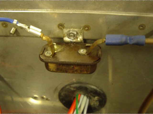
Rescued attachment v-r-and-fuel-gauge-s.jpg
|
|
|
johnjulie
|
| posted on 19/8/05 at 07:11 AM |
|
|
You need the one that produces approx 9V. It is designed to feed both the fuel and temp gauge together.
Cheers John
JFDI
"Just F*****G Do It"
|
|
|