ditchlewis
|
| posted on 10/10/05 at 07:50 AM |

|
|
indicators dont work any ideas?
I have just finished wiring up all my lights.
As I progressed with the indicators I used the hazard switch to check that all the indicator lights were working.
So emagin my supprise when I turned the engine on and tried the lights, all worked except the indicators.
So off came the skuttle and the dash, I checked all the wiring and its correct. I replaced one or two connections that did not pass muster. All
correct and accounted for.
I know that it is not the flasher unit as the hazard lights work perfectly.
could it be the stalk unit. the dipped and main beam units work but how would i check if the indicator motion works?
I know it is a lond shot but any one have any ideas before i spend another weekend tracing every connection
the wiring loom is a vickie green loom if that helps.
Hoping you may have some ideas.
regards
Ditch
|
|
|
|
|
BKLOCO
|
| posted on 10/10/05 at 08:12 AM |
|
|
There is an error on that loom diagram.
I would hazzard a guess that you are using the later type Sierra switches with lighting relays.
I will check what the error is as I can't quite remember. I went through the same sequence and ended up tracing the whole of the indicator
circuits. I think that the error revolves around the fact that the indicator switch does NOT switch a live supply to the flasher relay but the
hazzards do.
I'l check and get back to you.
Experience is what you get when you don't get what you want!!! 
|
|
|
BKLOCO
|
| posted on 10/10/05 at 08:15 AM |
|
|
Just remembered there is also an error with the washer circuit. I think the sierra switch switches to earth but the loom is wired to switch the live.
Experience is what you get when you don't get what you want!!!
|
|
|
Peteff
|
| posted on 10/10/05 at 08:42 AM |
|
|
There are two black wires to the left switch and one of these goes to the flasher. If you already have them connected try swapping them over. Do you
get indicators but they don't flash?
yours, Pete
I went into the RSPCA office the other day. It was so small you could hardly swing a cat in there.
|
|
|
hobbsy
|
| posted on 10/10/05 at 08:52 AM |
|
|
Random thought - you're not using LED bulbs are you? As they usually don't draw enough to allow the flasher to work. So you have to
fit resistors in line... thats why mine don't work at the moment anyway 
|
|
|
BKLOCO
|
| posted on 10/10/05 at 09:20 AM |
|
|
Here is the corrected drawing.
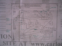 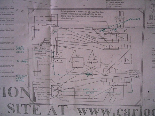
Description V G wiring errors
If you pressed the w/s/ wash while you had it connected up as original then you have probably blown a fuse. Check first.
Just looked at my notation. on the left when I say move from here to here I am talking about the BLACK with X through it black & yellow stays
where it is. The black at the bottom is drawn wired to the wrong plug.
I hope this all makes sense. If not were not far away, your welcome to come over and have a look.
Experience is what you get when you don't get what you want!!!
|
|
|
donut
|
| posted on 10/10/05 at 09:52 AM |
|
|
quote:
I would hazzard a guess
Very good!! 
Andy
When I die, I want to go peacefully like my Grandfather did, in his sleep -- not screaming, like the passengers in his car.
http://www.flickr.com/photos/andywest1/
|
|
|
Dusty
|
| posted on 10/10/05 at 09:59 AM |
|
|
Hazards are powered through the column switch off the horn supply H(30) which is constant live. Indicators are powered from pin 54 into the switch
which is ignition live and out of the switch at pin 49 which should thus be ignition live to pin 49 on the indicator relay. Thus pin 49 on the relay
should have an ignition live supply from the switch. The hazard switch disconects this ignition live supply when it is switched on, replacing it with
the horns constant live.
Test the relay base that pin 49 on the indicator relay plugs into with the ignition on. Should be live. If not check its connected back to pin 49 on
the column switch and that pin 54 on the column switch has an ignition live supply and if not give it one.
|
|
|
ditchlewis
|
| posted on 10/10/05 at 10:04 AM |
|
|
Many Many Thanks!!!!!!
I have to admit to being a total electrical Numpty, it was always the thought of the electrics that put me off building a car long ago.
I realy do wish I had found this site earlier in the build process.
I actually live closer as i now live with my fiancee in Caple st Mary and I commute to Chelmsford every day.
I may well take you up on your kind offer and have a look if i cannot make it work now.
Regards
Ditch
|
|
|


.jpg)