
Another EXUP question.....sorry!
Adam - 17/7/07 at 03:15 PM
I've done search's on this topic and my understanding is unless you don't want error codes on your dash then it's best just to fit
the motor under the dash.... is this the case?
I'm fitting a 2000 R1 motor and just wondering if i need to fit it, plus was wondering if you can hear the motor under the dash? is it
annoying?
Sorry if this has be answerd else where but i just can't find the info  be gentle with me i'm still learning
Cheers
Adam
[Edited on 17/7/07 by Adam]
nitram38 - 17/7/07 at 03:18 PM
Are you using the R1 clocks?
If not, then remove all together
fesycresy - 17/7/07 at 03:20 PM
Mines under the dash.
Never ever hear it. The intake and exhaust noises drown it out.
HTH
Lyn.
stuart_g - 17/7/07 at 03:21 PM
Why not fit the EXUP motor in the engine bay? then it won't really matter, mind you though I don't think you will hear it regardless of
where it is put.
Adam - 17/7/07 at 03:22 PM
I plan to use the R1 clocks as there doesn't seem much options without spending a fortune.
Cheers
Adam
Adam - 17/7/07 at 03:23 PM
thanks for the reply guys.... that was bloody quick
Many thanks
Adam
nitram38 - 17/7/07 at 03:26 PM
There is supposed to be an electronic diagram somewhere on the web, but I have also heard that it does not work all that well.
adithorp - 17/7/07 at 03:27 PM
I've just made up the widget suggested by BobC in this thread.
http://www.locostbuilders.co.uk/viewthread.php?tid=69965
Works a treat and I'm not lugging a redundant EXUP around, or I won't be when I get on the road!
Adrian
[Edited on 17/7/07 by adithorp]
nitram38 - 17/7/07 at 03:28 PM
Just found this link
zxrlocost - 17/7/07 at 04:07 PM
Hi unless you want tto remove it altogether just leave it plugged in in the engine bay
smart51 - 17/7/07 at 04:12 PM
Mine is in the engine bay. It squeaks at key on and key off, but not loudly. You can't hear it over the noise of the engine.
Bob C - 17/7/07 at 05:15 PM
Holy mackerel - did you see the cost of that system in nitram's link - $100 + p&p & import duty. I bet it's that same as my circuit
inside (cost about 10p). Sounds like you gave up in the end smart51 - I wonder what's the matter with yours, mine works 100% & so do all the
others I know about.... (though maybe some people aren't telling me..)
Bob
adithorp - 17/7/07 at 08:43 PM
Think you ought to go into production, Bob!
Johneturbo - 21/2/08 at 05:18 PM
Could someone do me a real simple diagram for this cure, as i dont have the EXUP valve with my engine kit, so i'm stuck with error code 17 on the
dash
or maybe Bob the invertor could make me one, for a small fee
cheers
john
adithorp - 21/2/08 at 08:37 PM
Bob Exup widget
http://www.locostbuilders.co.uk/photos.php?action=showphoto&photo=exup.GIF
If I can make one then anyone can!
adrian
Johneturbo - 21/2/08 at 09:08 PM
quote:
Originally posted by adithorp
Bob Exup widget
http://www.locostbuilders.co.uk/photos.php?action=showphoto&photo=exup.GIF
If I can make one then anyone can!
adrian
I knew you was gona say that!
do you have a pic of yours? and the parts i need from maplins, as i'm not sure what some of the symbols mean
cheers.
john
adithorp - 21/2/08 at 10:05 PM
Neither had I.
I'll have a look tommorow. I've got a spare set of bits in case my first attempt didn't work. I'll photo them and the finished
thing if I get time.
adrian
Johneturbo - 21/2/08 at 10:37 PM
That would be mucho great if you can.
but no worrys if you don't have time.
i'll also print of that diagram and take it to maplins, and see if i get lucky!
adithorp - 21/2/08 at 11:35 PM
Maplin don't do a BC 847 - try a BC 547 - according the BobC almost any general purpose small signal npn transistor will do. For the capacitor I
used an aluminium electrolytic, anything from 16V upwards will do (again had to ask Bob; I didn't have a clue!) You'll also need some strip
board and a small box (matchbox sized) to put it in.
If it sounds like I know what I'm talking about with electronics...I DON'T!
adrian
Bob C - 21/2/08 at 11:41 PM
Hope it works for you - as I said above, mine works & several others have had success, but smart51 had trouble & he's clearly no stranger
to electronics. Hey it's as small and easy as circuits get - have a go! As long as the resistors are in circuit on the inputs (and not shorted to
deck or each other) you shouldn't blow anything up!
The circuit was done because I thought the one on "bike engine transplant central" was way over complex.
If you lived a bit closer I'd give you a hand with it (would have done with Adithorp but he nailed it first time!)
Bob
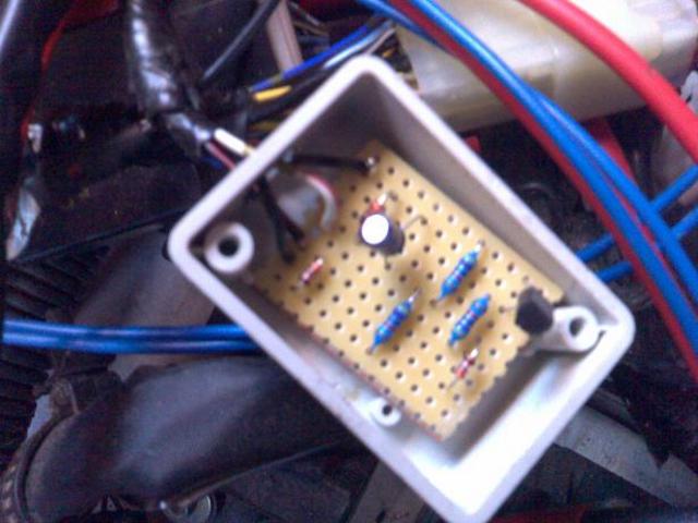
Bob C - 21/2/08 at 11:49 PM
PS here's a photo of mine. There's an extra resistor in this circuit to pretend to be some fuel in the bike tank!
The circuit is now smothered in hot melt glue to stop it oxidising (otherwise the copper of the stripboard disappears over a few years)

Rescued attachment exupcct.jpg
jimgiblett - 22/2/08 at 06:08 PM
For the non FI models I personally wouldnt bother. The bike clock give an error code (tacho tango) but this is only when the ingnition is on and the
engine not running.
Different matter for the FI engine as it displays on the clocks all the time. In which case one of Bobs wonderful circuits dues the job.
Dont stick the mototr behind the dash get a circuit like Bobs. Then you can sell the exup unit and drink beer on the proceeds. Bob I still owe you a
couple of beers now
- Jim
Bob C - 22/2/08 at 07:44 PM
hey Jim - it worked then!
Shame you're the other end of the country, I could just do with a couple of beers.......
Bob
adithorp - 22/2/08 at 09:52 PM
Just don't collect all these owed beers at the same time or you'll be pissed!
adrian
adithorp - 22/2/08 at 11:12 PM
Some pictures as promised.
Forgive the diagram Bob (and any one else that understands electronics) but converting you diagram to fit on the strip board was the tricky bit for me
so I've included it for anybody elses benefit who's as dense as me with these things!
http://i189.photobucket.com/albums/z282/adrianthorp/fury044.jpg
http://i189.photobucket.com/albums/z282/adrianthorp/fury046.jpg
http://i189.photobucket.com/albums/z282/adrianthorp/fury047.jpg
http://i189.photobucket.com/albums/z282/adrianthorp/fury045.jpg
adrian
Johneturbo - 23/2/08 at 06:55 PM
Cheers adrian, that diagram is a great help for my feeble brain.
and well done for keeping the receipt, i seem to loose them before i leave the shop.
i'll have a go at this next week
adithorp - 23/2/08 at 11:11 PM
The recipts are for enough bits to make 2. Just incase I f*&%$d up the first attempt.
adrian
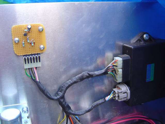
Johneturbo - 29/2/08 at 03:19 PM
I made bobs box of tricks. and it worked!
even with my lack of electricary skills
thanks bob. and adrian for that simpler diagram to follow.
here's a pic of my creation

Rescued attachment exupBoard.jpg
Bob C - 29/2/08 at 07:37 PM
Looks mint Johnnie!
I'd run it for a while, til you're confident, then pot it in bathroom sealant or something like. Otherwise 1) eventually the wires will work
harden and break near where they're soldered to the board and 2) the copper foil on the stripboard will corrode away in time.
Nice neat job, nice wee box, great!
bassett - 17/7/08 at 05:53 PM
sorry to bring up an old thread guys but which bits need soldering together as im useless at reading wiring stuff and want to do it right.
cheers
bones - 7/6/09 at 09:33 PM
Just got round to making one of these for my BEB after ditching the constantly sticking EXUP.
Great write up fellas, worked first time.
Got me in the mood for maybe trying a home made shift light, so had a poke around and found a possible starting point. Anyone had a go at this yet?
Cheers.


