Tralfaz
|
| posted on 21/4/09 at 11:25 PM |

|
|
Chassis drawing (Comments)
Before you say to yourselves, "Great another chassis drawing, why do people always try to reivent the wheel..."
Here is the story.
My Seven is about 80 percent done (after 8 years or so).
The chassis was essentially a self designed/drawn copy of the Caterham Dedion chassis but modified to have an MX-5 based IRS.
As the chassis was designed and built at the same time and has been altered in the process, it is less than ideal.
Further I would like to think I have learned something in the interim.
So, I plan on redoing the chassis. Some parts will be recycled and a jig will be made to keep all the suspension pickup points where they are. I
think I should be able to do this all pretty quickly and easily. I have most of the steel I need, and completing the car isn't really on the
horizon until finances improve...
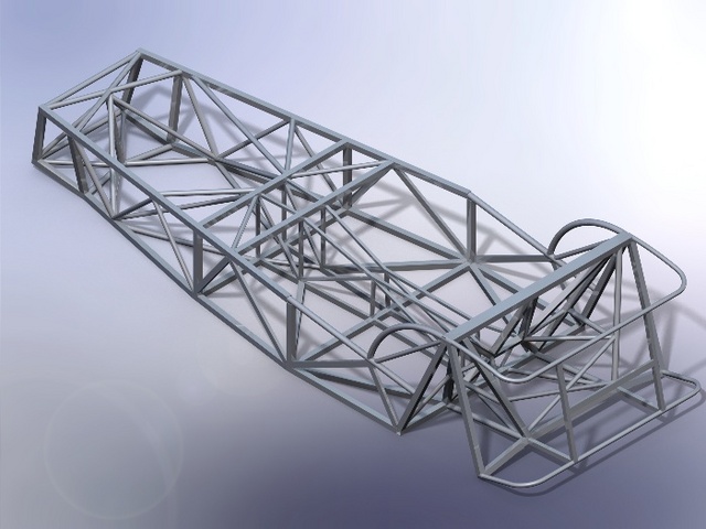
This is what I have come up with, the trained eye will see shades of the Series III, and the CSR chassis and some things I have added.
Solidworks says 132 lbs.
Any glaring problems?
Thanks
T
PS The car will be bike engined and as a result the (missing) upper engine bay diagonal won't fit.
Description
 
Description
[Edited on 21/4/09 by Tralfaz]
|
|
|
|
|
alistairolsen
|
| posted on 21/4/09 at 11:39 PM |
|
|
diagonalsin the front frame and the sideframes where the rack exits would be worthwhile.
Otherwise seems good. What tubing is that from for 132lbs?
|
|
|
james h
|
| posted on 21/4/09 at 11:41 PM |
|
|
The tunnel top should have cross pieces?
|
|
|
handyandy
|
| posted on 21/4/09 at 11:41 PM |
|
|
looks nice , only thing i can see to poss help is the two diagonal braces in the floor where the driver & passengers sits, would it not help if
those two braces where straight across from outside chassis rail to the trans tunnel rail ? my reason would be to aid strong mounting points for the
seats, i know that the triangle is used cos of strength etc but just a thought.
best of luck with the chassis.
cheers
andy
|
|
|
muzchap
|
| posted on 21/4/09 at 11:53 PM |
|
|
Nice solidworks 
My only comment and that's purely as an observation of my chassis (Luego) is that on the rear where the diff mounts - they have cut triangular
plate and welded across
They have also done the same on the transmission tunnel at the rear - If you want to send me the solidworks file - I'll add them in for you, or
I can just save your JPG and photoshop - whatever works best for you U2U if you do decide to take me up on the offer
Good luck with the project!
P.S - Just read Als post - indeed the top of the transmission tunnel should have horizontal bracing bars.
P.P.S On my chassis they have incorporated a front bar for the steering rack to bolt too - works really well...
[Edited on 21/4/09 by muzchap]
------------------------------------
If you believe you're not crazy, whilst everybody is telling you, you are - then they are definitely wrong!
------------------------------------
|
|
|
Tralfaz
|
| posted on 22/4/09 at 01:57 AM |
|
|
Cheers Mates
I actually have the top of the tunnel closed off in the main 3D sketch, but forgot to extrude the profile (weldment) so it doesn't show up in
the render.
muzchap, I had a look at the pics in your archive and see the bits you are talking about. I will be adding some reinforcement when I decide on which
diff to use. I had an MX-5 unit in the MK1 chassis, but considering an S2000 one for the new frame as it is a smaller package.
T
|
|
|
Steve Hignett
|
| posted on 22/4/09 at 07:14 AM |
|
|
Have you "placed" your engine and exhaust "into" your chassis at the correct height and angle to ensure it fits etc?
|
|
|
Tralfaz
|
| posted on 22/4/09 at 07:12 PM |
|
|
I have fit a CAD file of the R1 into the drawing and it fits fine(snug though). The angle of the propshaft is my only concern. Right now it is
approximatley 5 degrees, though I think with only a few minor alterations I can get it down to 4 or so, which I think will be fine as long as I treat
it as a regular maintenance item.
As for the header, I shouldn't have any trouble making one to fit, unfortunately the one I have already made for the Mk1 chassis will likely not
work, but I am not completely pleased with it anyway..so no worries.
Thanks
T
|
|
|
muzchap
|
| posted on 22/4/09 at 10:20 PM |
|
|
Hi Mate,
The S2000 diff is awesome - very flat and low so gives good balance to the car. In the UK it's also LSD via planetary gears or something -
according to the Honda workshop manual 
I got mine pretty cheap - £100
I still had the ford hubs - so I've drilled the S2000 half shafts and put the fords in, welded, pinned and welded again - they are super strong
If you need any specific dimensions from the chassis let me know - as I'm starting to progress with the build now and will soon be chucking the
panels back on
I got sidetracked with the Elise and CRF450
Cheers,
Murray
------------------------------------
If you believe you're not crazy, whilst everybody is telling you, you are - then they are definitely wrong!
------------------------------------
|
|
|
JoelP
|
| posted on 24/4/09 at 04:36 PM |
|
|
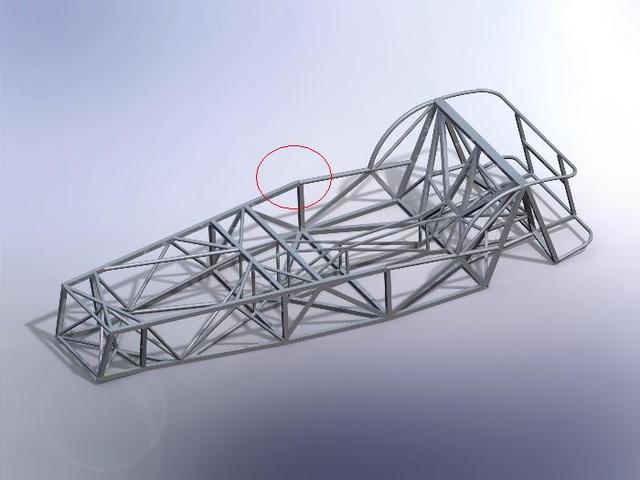
this part (circled below) always strikes me as a weak spot in LSIS chassis in general.
Not sure what you can do with it though. I once tried designing a chassis that had the top rail straight and continuous from front to back, but it
doesnt lend itself to the seven shape really. Another way to make up for it would be to make the trans tunnel structural, but its quite awquard making
the rear shock mounts feed force into the trans tunnel!
Do like the rest of it though.
Rescued attachment Bare4.jpg
|
|
|
Tralfaz
|
| posted on 24/4/09 at 10:03 PM |
|
|
quote:
Originally posted by JoelP
this part (circled below) always strikes me as a weak spot in LSIS chassis in general.
Not sure what you can do with it though. I once tried designing a chassis that had the top rail straight and continuous from front to back, but it
doesnt lend itself to the seven shape really. Another way to make up for it would be to make the trans tunnel structural, but its quite awquard making
the rear shock mounts feed force into the trans tunnel!
Do like the rest of it though.
Thanks for the comment.
Might consider some gusseting and perhaps insert and weld a 7/8" tubing sleeve inside the joint.
Kind Regards,
T
|
|
|