mr henderson
|
| posted on 18/5/09 at 07:29 PM |

|
|
An inexpensive way of checking (4) wheel alignment and camber
Equipment required-
2 lasers with vertical line and horizontal line (ideally also self-levelling), I used these from Screwfix, £62 odd the pair
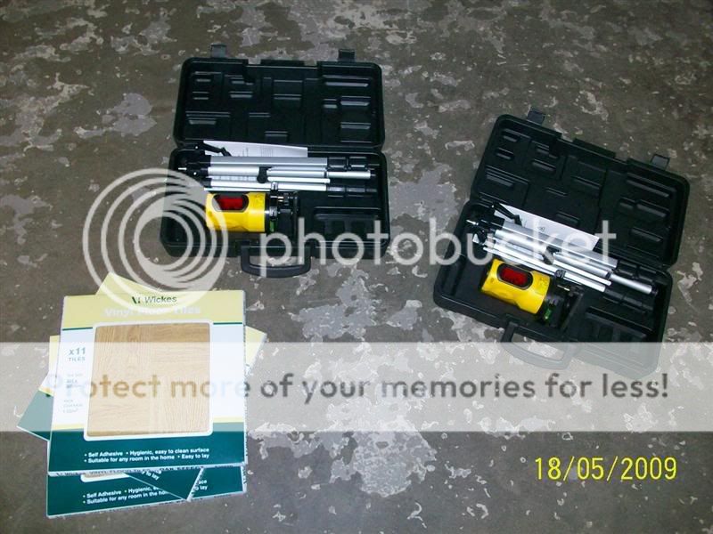
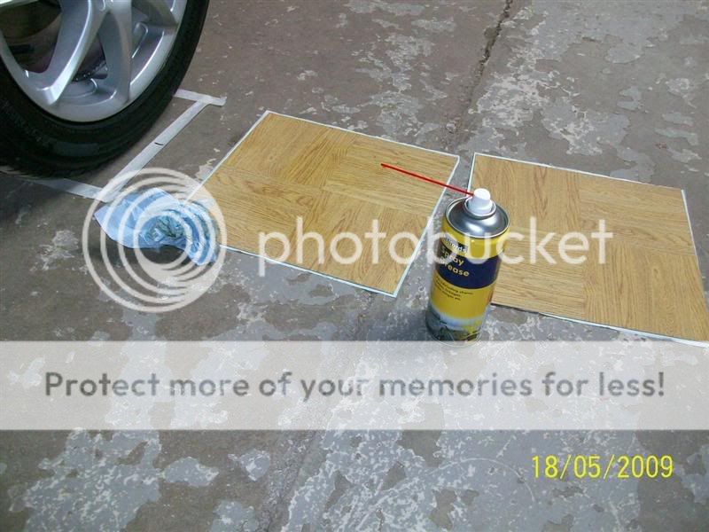
Several vinyl floor tiles (could be as many as a couple of dozen, 8 is the theoretical minimum)
A hard surface (either indoors or you will need to do this after dark)
Decent steel ruler
Decent spirit level (to check the lasers)
A batten about 2 metres long
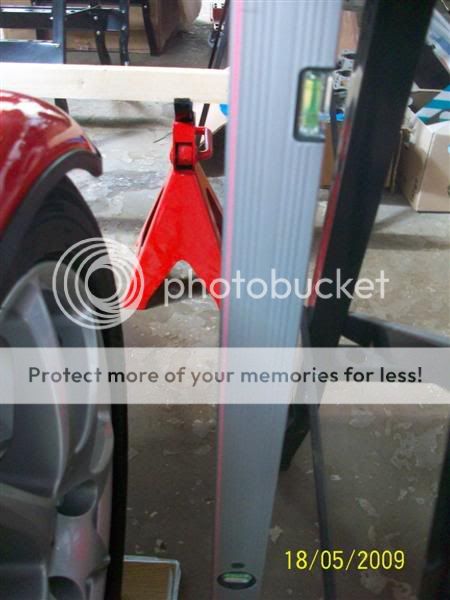
2 axles stands or similar
Various other bits and pieces
Before starting- you will wish to check that the suspension is riding at your required height, and some adjustment of the springs might be required to
achieve this. If youve got or can get some corner weight scales then now would be the time to use those as well.
Method
Move the car into position
Mark a square on the floor around each tyre
Move the car away again
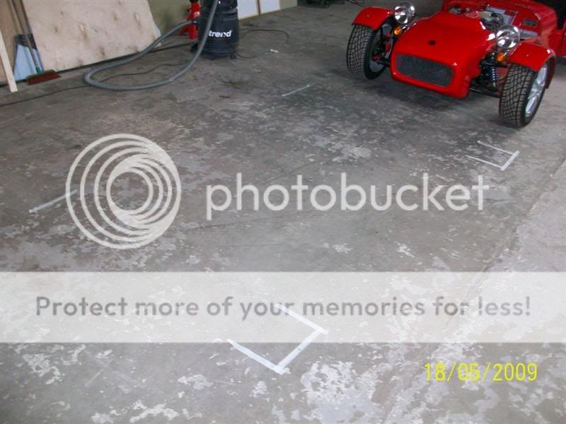
Use the horizontal line on the laser to check the floor height at each marked square
Find the highest square and place 2 vinyl tiles on it This is important
Go to the next highest square and place sufficient tiles on it to make it level with the first one. The tiles I am using are about 1mm thick, but Im
using a marked line on a spirit level and just adding tiles until the line comes up to the laser level line.

Repeat on squares 3 and 4
Write down how many tiles have been placed on each square
Move the tiles away from each square
Roll the car back into position
Jack up each corner in turn, and place the correct number of tiles in the square so that when this has been done at each corner, the car will be
standing on a level surface. At each of the front corners, before placing the tiles under the wheel, put some grease or oil between two of them (this
will allow them to act as swivel plates)
If all this has been done correctly the car will now be standing on a level surface, and that is a vital requirement of this procedure. If you havent
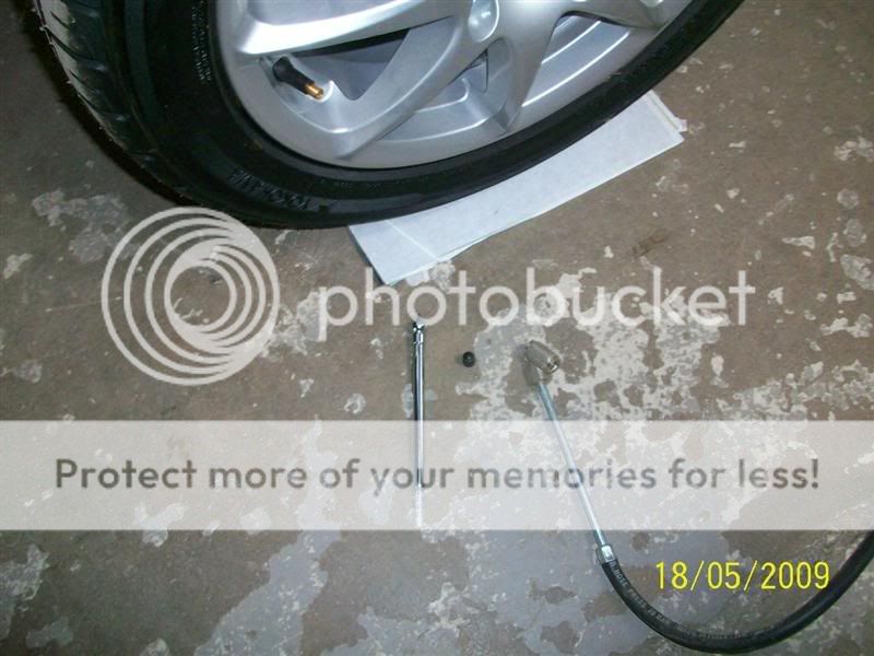
done so already, set the tyre pressures
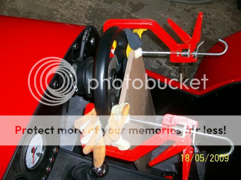
Also important is to ensure that the steering wheel is in the straight ahead position, and to find a way of fixing it like this. Note the padding to
prevent the wheel being marked.
Now it is time to set up the lasers. The idea is to create two parallel and vertical lines, one each side of the car, equidistant from each side and
parallel with the cars centreline. It wont matter if there is any difference in the width of the front and rear axles. The car in the pictures is a
Tiger Avon, Cortina based front with Sierra based rear, and the rear is wider than the front.
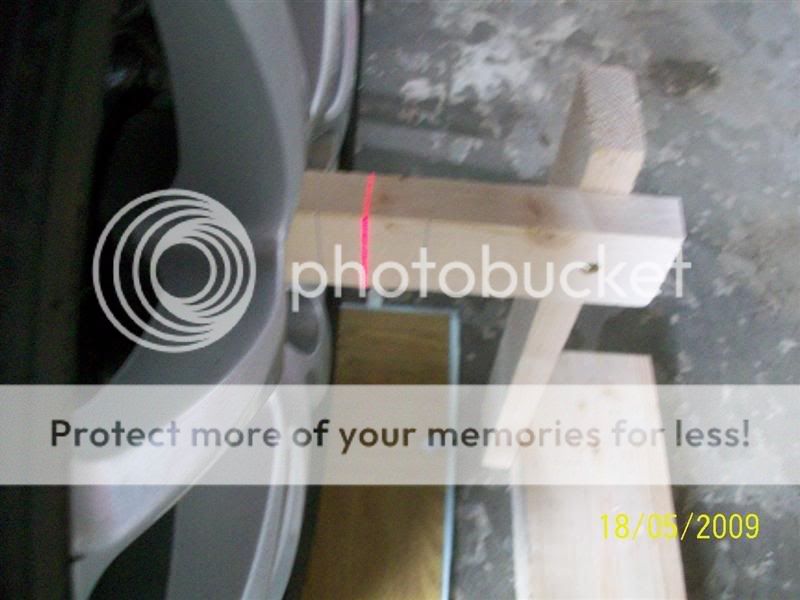
Now you need to make up a couple of wood (or whatever) markers which can be placed against each rear hub. They need a square end and a line marked at
a suitable distance to the square end. The purpose of these is for us to be able to provide lines which the lasers can line up with equidistant from
the hub on each side. They also save having to keep checking the distance (there will be plenty of that later). Make sure the side that faces the
lasers are in line with the middle of the hub. The centre line on the pic below can't be seen as the laser line is right over it.
Now we need to mark a batten with lines that are the same distance apart as the lines on the markers mentioned above. With the lasers this is easy,
just hold a batten across the car (on the Tiger I had to hold it over the roll bar) along the axle centreline, then mark lines where the lasers strike
it. Now we have a reference for the parallel lines this procedure depends on.
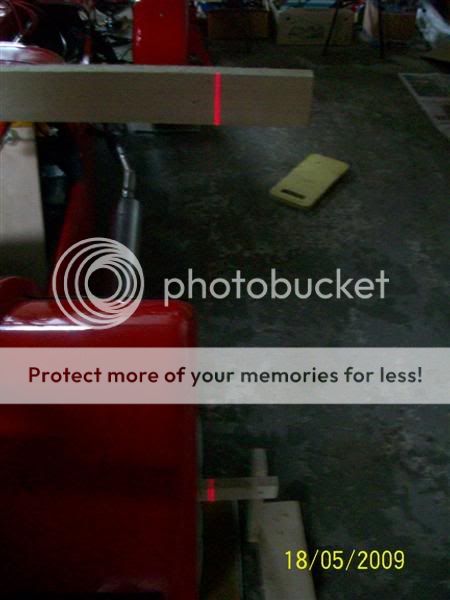
The batten needs to be placed on stands at the far end of the car. Try to line it up with the cars centreline as this will speed the next step.
Now comes the tedious part, but it needs to be done carefully as the accuracy of the tracking checks will rely on us establishing two parallel lines
which align with the centreline of the car.
With the lasers switched on, move each one so that it shines a line on the rear wheel marker and on the batten at the other end, in both cases on the
marked lines. This is quite tricky as the lines will more a LOT with each small movement of the laser (makes a joke of those films where you see the
laser dot of the snipers rifle steady on the chest of his target several hundred metres away). Both the tripod and the laser itself will need to be
moved.
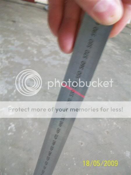
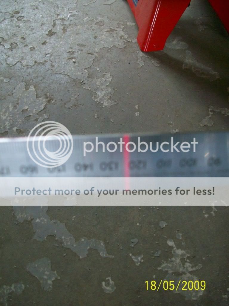
When the lasers are lined up with their targets go to the front wheels and measure from the centre of the hub to the laser line. Make a note of the
reading and then do the same on the other side. Now you need to move the lasers and the batten until you get the same reading on each side. I actually
pulled the car over slightly to get the last millimetre of the adjustment.
When the lasers have been checked and adjusted to ensure that they are parallel with the centreline of the car you are ready to start your wheel
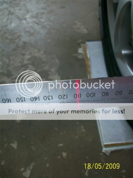
alignment and camber check. To measure camber, simply measure from the top of the wheel rim to the laser line, and then from the bottom of wheel rim.
It will help your accuracy if you make marks on the wheel rims in line with the centre of the hub, and find a way of ensuring that you are holding the
steel rule horizontally when taking the measurements. The laser lines have some thickness, it will be up to you whether you choose to read one side of
the line, or the middle. As long as you are consistent, it wont matter.
If you want the answer in degrees, you will need to do some trigonometry to convert the difference in distance, or maybe someone who knows about that
stuff could do a spreadsheet. On most IRS cars you can, and must, check the rears as well. If you are still building it would be a good idea to do
this before you fit the rear wings.
The toe is measured in a very similar way, only now you are comparing the distance from the front of the wheel rim to the rear, at 9 0clock and 3
oclock respectively.
Quite a difference with the rear reading-
If you wish, you can now set the toe to the required amount if your measurements show that this is necessary. The greased tiles will allow the wheel
to turn easily as you adjust the track rod.
If you anticipate doing this procedure again, you will want to keep a permanent record of the position of the squares on the floor, and how many tiles
are needed in each square to get them level.
Im not going to make any recommendations as to settings. When I checked the car in the pictures I found that the camber was sufficiently correct to
be left as is. With this car (and many others) the camber can only be adjusted in increments of 1.5mm because that is the thread pitch on the Transit
ball joint, and needs to be in full turns unless you have fitted those funky camber adjusters. In fact the affect of a full turn will be amplified
because the ball joints are closer together than the rim of the wheel.
The toe I decided to set at 0 degrees, being the average of the desirable slight toe in normally wanted on this type of car, and the toe out which
help self-centring on many cars (this car hasnt been IVA tested yet). I might experiment with some toe out if the car shows to have poor self
centring when tested.
Incidentally, I did test the lasers for accuracy, and they were spot on
John
[Edited on 18/5/09 by mr henderson]
|
|
|
|
|
dinosaurjuice
|
| posted on 18/5/09 at 07:42 PM |
|
|
excellent guide, cheers john
|
|
|
oldtimer
|
| posted on 18/5/09 at 07:55 PM |
|
|
I'm impressed - good post.
|
|
|
roadrunner
|
| posted on 18/5/09 at 08:01 PM |
|
|
WOW. All i need to do now is to find a garage as big as yours 
|
|
|
Mark G
|
| posted on 18/5/09 at 10:02 PM |
|
|
I do a similar way but instead of using lazers I just put an axle stand in each corner of the car and tie fishing wire between the front and rear
stands on both sides.
Make sure the wire is parallel with the sides of the car by measuring from the wheel hubs and checking the distance between the two wires are equall
front and rear.
Then just measure from the wire to the front edge and rear edge to work out your toe.
|
|
|
mr henderson
|
| posted on 19/5/09 at 12:21 AM |
|
|
quote:
Originally posted by Mark G
I do a similar way but instead of using lazers I just put an axle stand in each corner of the car and tie fishing wire between the front and rear
stands on both sides.
Make sure the wire is parallel with the sides of the car by measuring from the wheel hubs and checking the distance between the two wires are equall
front and rear.
Then just measure from the wire to the front edge and rear edge to work out your toe.
I did consider that, as the method described above is based on it, but doing it with the lasers allows the camber to be measured as well (plus means
there nothing for me to trip over )
[Edited on 19/5/09 by mr henderson]
|
|
|
RK
|
| posted on 19/5/09 at 01:52 AM |
|
|
Good information, if nothing else, it confirms that I would rather have someone experienced and knowledgable doing that sort of thing. I got confused
after "check tyre pressures..." but looks impressive!
|
|
|
mr henderson
|
| posted on 19/5/09 at 06:52 AM |
|
|
quote:
Originally posted by RK
Good information, if nothing else, it confirms that I would rather have someone experienced and knowledgable doing that sort of thing. I got confused
after "check tyre pressures..." but looks impressive!
I don't see how you can claim, after all that you have done with home-made car type stuff, not to be experienced and knowledgeable.
John
|
|
|
nick205
|
| posted on 19/5/09 at 08:20 AM |
|
|
Excellent post John - really useful stuff. even if you're not doing it yourself it helps to understand how and what is being measured and
adjusted.
Added to my favourites 
|
|
|
Frosty
|
| posted on 19/5/09 at 11:12 AM |
|
|
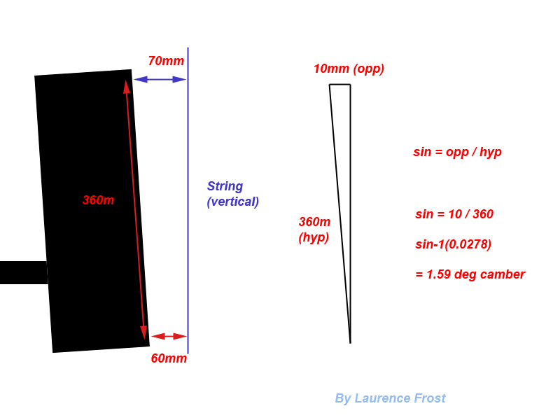
To work out wheel camber is very simple, you need to first of all measure the overall size of the wheel face. Typically this will be from one edge of
the rim to the other, so slightly over the actual size of the rim.
So a 13 inch wheel will be around 360mm (14.1 inches)
Now hang some string vertically about 10cm away from wheel (best with a weight at the bottom to pull it tight).
Measure from top of rim to the string, write it down, then measure from the bottom of the rim to the string. If you subtract the larger (top) from the
smaller (bottom), you will get the length of the top of the triangle.
So if you measured wheel face of 360mm, and 10mm difference to the string between top and bottom of the wheel, you know the hypotenuse and the
opposite.
So to find the bottom angle, do Inverse sin (10/360) which will give you 1.5 degrees of camber.
The image will help:
|
|
|
mr henderson
|
| posted on 19/5/09 at 01:02 PM |
|
|
Probably better than the string method is to use a spirit level with 2 spacers of known thickness to touch the rim at the top and the bottom. If the
wheel is not vertical, there will be a gap at either the top or the bottom when the bubble in the spirit level is centred. This gap can then be
measured (drill bits are good for this).
The string or this method won't be accurate, of course, unless the car is levelled first, a way of doing this is mentioned in the first post on
this thread, alternatively a water level can be used.
John
|
|
|
Frosty
|
| posted on 19/5/09 at 01:19 PM |
|
|
quote:
Originally posted by mr henderson
Probably better than the string method is to use a spirit level with 2 spacers of known thickness to touch the rim at the top and the bottom. If the
wheel is not vertical, there will be a gap at either the top or the bottom when the bubble in the spirit level is centred. This gap can then be
measured (drill bits are good for this).
The string or this method won't be accurate, of course, unless the car is levelled first, a way of doing this is mentioned in the first post on
this thread, alternatively a water level can be used.
John
I agree - if the car is not on level (or very near to level) ground then the string method will be out by as much as the ground is.
But then I would assume (or hope) that anyone setting up their car would use level ground otherwise they are just wasting their time.
Good write-up BTW.
|
|
|