Mix
|
| posted on 14/4/04 at 08:37 AM |

|
|
I'm not a suspension whizz kid, the following are just my 'feelings' about what may have caused the failures.
In my opinion the loads that have caused the tube to bend are more likely to be in the direction of trying to push the wheel backwards, (hitting kerb,
heavy braking ?).
My thinking behind this is as follows:
For the failure to be caused solely by the weight of the car, the vertical force required to bend the wishbone in this manner would be using the
suspension lower mount as it's fulcrum. Therefore unless something has siezed / bottomed the suspension would move to relieve the load.
If however the wishbone was to receive a force trying to push it backwards the natural tendancy would be for it to bend at it's weakest point,
and away from the vertical force being applied by the weight of the car. This seems to be what has happened.
Or am I just talking B******s ?
Mick
|
|
|
|
|
kingr
|
| posted on 14/4/04 at 09:54 AM |
|
|
My suspicion is that the damage was caused by a ball joint reaching the end of its travel - I'd check the maximum travel by removing the coil
over and lifting the whole assembly manually and seeing what locks up first and where.
I would suggest that's it's not braking - the damage is not what I would expect given the forces applied during braking.
Kingr
|
|
|
Bob C
|
| posted on 14/4/04 at 11:44 AM |
|
|
I don't buy pivot stiffness - it would bend near the stiff end (!) and you'd never get the bolt in & how can a metalastic joint be
stiff - it's just rubber flexing. Ball joint limit could be it but that looks unlikely too, the bending moment would be at least double near the
bottom ball joint, also it's traditionally the uppers that bind. From what Chris said about the actual incindent the tube faied in compression!
If the brakes are on 1) caliper torque reactiion on front upright is compressing this tube; 2)braking force is compressing this tube; 3) a right hand
bend is compressing this tube. A buckling in compression would occur in the middle of the tube and it would buckle downwards because 1) the spring is
pushing it that way and 2) that long weld where the plate joins will have warped the tube to have a "belly down " bend anyway.
OK I guess it was a combination of the compression and bending due to beam stress.
I'm right at the point of making my own lower front wishbones & this has been such a valuable "wake up call"
Cheers dudes
BobC
|
|
|
DaveFJ
|
| posted on 14/4/04 at 12:07 PM |
|
|
dare I be the one to suggest that these wishbones "supplied by a locost parts specialist " are possibly from Lolocost ??
I think we all have opinions on their products........
I also do not 'buy' the pivot point as being the cause - for the similair reasons.
I think a lot of insight could be gained from jacking the car up and removing the springs/dampers completely and then examing the full range of
movement ( not forgetting to check throughout the range of travel of the steering as well!)
My best guess (reasonably pointless based on a single photo) would be that it is a combination of the various attributes of the geometry that are
causing a ball joint to reach its maximum angle.
Just an after thought... You say he was going into a bend? was by any chance braking heavily ? the difference in the bend in the 2 sides of the
wishbones imply a twisting moment. A combination a big brakes/sticky rubber/heavy car would put some abnormal twisting loads on the wishbones which
would add to a basic weakness in the design could lead to this failure ? - just a thought..
HTH
[Edited on 14/4/04 by protofj]
Dave
"In Support of Help the Heroes" - Always
|
|
|
Chris_G
|
| posted on 14/4/04 at 12:20 PM |
|
|
quote:
dare I be the one to suggest that these wishbones "supplied by a locost parts specialist " are possibly from Lolocost ??
The original wishbone as seen in the photo very much appeared to be home made. The one that has just gone was not from Lolocost but I can't
remember the name - "something Engineering" from up north somewhere, I'll find out and let you know. It wasn't one of the main
suppliers who all seemed to not be bothered about supplying a couple of wishbones, they were only interested in selling full kits etc!
Chris
|
|
|
ned
|
| posted on 14/4/04 at 12:48 PM |
|
|
was it daniels engineering?
Ned.
beware, I've got yellow skin
|
|
|
Chris_G
|
| posted on 14/4/04 at 01:42 PM |
|
|
That's it Ned, Daniels Engineering as seen here:
http://web.ukonline.co.uk/members/p.dunn2/new%20web%20page/Locost%20Parts/pictures/depics/traillingset.jpg
Remember though, this wishbone has not failed anywhere near as badly as the one allready shown, but then the car has only been driven on public roads
with lighter wheels etc and no track work at all!
Chris
|
|
|
britishtrident
|
| posted on 14/4/04 at 01:50 PM |
|
|
To summerise:
(1) The primary mode of failure was bending from vertical load with additional compressive loads from cornering.
(2) Inital failure initiated by buckling of tube wall.
(3) Failure occured at stress raiser formed by right angle corner formed between plate and tube.
(4) This stress raiser was very close to point of max bending moment
Course of action to avoid future failures
(1) Use tube of slightly larger diameter to increase stiffness and strength in bending.
(2) Use slightly thicker tube to increase ressistance to localised buckling and give a small increase in stiffness and strength in bending.
(3) Re-design plate to reduce angle at which plate meets the tube to reduce the stress concentratio factor and move the corner away from point where
max bending moment occurs.
(4) Carefully dress the ends of the welds between the plate and tubes to reduce the stress raising effect.
Notes
(1) If desired DOM tube will give some addional strength but not any increase in stiffness.
(2) Use of oval tube will give little or no structural benefit.
[Edited on 14/4/04 by britishtrident]
[Edited on 14/4/04 by britishtrident]
|
|
|
type 907
|
| posted on 14/4/04 at 06:55 PM |
|
|
Hi all,
Looking at how compressed the spring is, I'm wondering what it looked like when the wishbone failed. Must have been almost closed. A
shock adsorber without the ability to adsorb shocks?
I'd also like to pick up on a point made by Bob C in that welding a plate on top of a tube tries to bend it upwards.
Is it not better to join onto a tube on it's centre line & fillet weld both sides.
(see pic). Just good engineering practice IMHO.
By the way, tube is 22.2mm dia, 2.5 wall, plate is 4mm thick, stainless.
Paul G
Rescued attachment w-bones s.jpg
Too much is just enough
|
|
|
cymtriks
|
| posted on 14/4/04 at 08:39 PM |
|
|
Just to expand on the bending vs strength posts I reckon the bending moment at that point is around 960 inch lbs. This gives the following safety
margins assuming a 3g bump and that the load is shared by two tubes:-
3/4 - 16g gives 0.75
3/4 - 14g gives 0.88
1.0 - 16g gives 1.42
1.0 - 14g gives 1.70
Less than 1.0 = bent wishbone
The solution appears to be to use 1 inch tube for the lower wishbones.
|
|
|
Mark Allanson
|
| posted on 14/4/04 at 09:05 PM |
|
|
BUGGER!! 
If you can keep you head, whilst all others around you are losing theirs, you are not fully aware of the situation
|
|
|
Rorty
|
| posted on 14/4/04 at 09:12 PM |
|
|
Well, that's about covered it!
Chris_G states the bushes were new and that lubrication wasn't an issue, but doesn't mention the accuracy of the chassis brackets, and Bob
C states:
quote:
I don't buy pivot stiffness - it would bend near the stiff end (!) and you'd never get the bolt in & how can a metalastic joint be
stiff - it's just rubber flexing.
Well, I've seen posts on this forum where people have mentioned using up the bush's pliability to distort enough to insert the bolt
through a misaligned chassis bracket. I know from experience it doesn't take much to persuade a pivoting joint to cease and desist.
I fully agree with Britishtrident's first post with relation to the stress riser. I should have elaborated in my first post that scenario is
likely to occur if a pivot is binding. I accept it may also happen even if the pivot is not binding!
Type 907 and Cymtriks have the answers.
Cheers, Rorty.
"Faster than a speeding Pullet".
PLEASE DON'T U2U ME IF YOU WANT A QUICK RESPONSE. TRY EMAILING ME INSTEAD!
|
|
|
britishtrident
|
| posted on 14/4/04 at 09:30 PM |
|
|
Failure in picture is nothing what so ever to do with pivots binding.
As has already been pointed out If binding was the cause the failure would occur where the tube is welded to bush eye as this is where the peak
bending moment would occur in this scenario.
In any case if a pivot was sezied I suspect the chassis bracket would be more likely to rip out.
[Edited on 14/4/04 by britishtrident]
|
|
|
Chris_G
|
| posted on 14/4/04 at 09:54 PM |
|
|
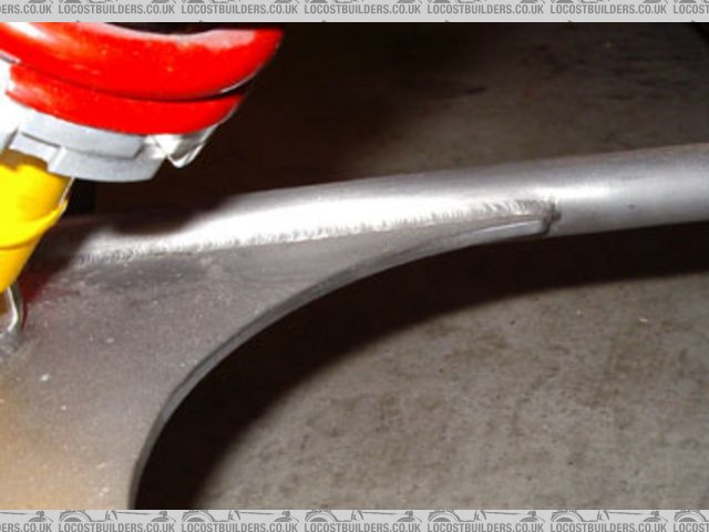
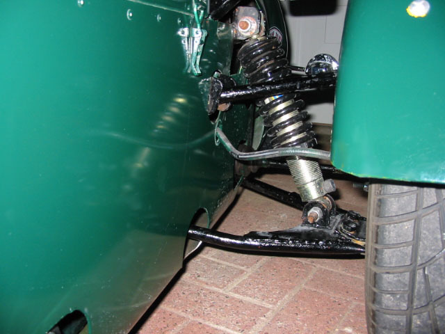
OK, here is a picture taken tonight of the new Daniels Engineering wishbone which has failed in a similar way but on the opposite side of the car. We
are sure that bottoming out is not occurring and something ammis in the geometry is the current favourite. We will have a look at the measurements
against the book at the weekend.
Chris
Rescued attachment New wishbone gone.jpg
|
|
|
britishtrident
|
| posted on 14/4/04 at 09:57 PM |
|
|
GTS wishbone
Rescued attachment bottombone.jpg
|
|
|
Bigfoot
|
| posted on 14/4/04 at 10:20 PM |
|
|
I stick to the comments in my first post. This has nothing to do with weight, binding or geometry. The second picture confirms that braking loads are
bending the tube. The part simply isn't strong enough. Britishtrident's comments on the design of the reinforcing plate seem reasonable,
why not just build a bigger stronger one?
I don't mean to critical of the SVA system in the UK, but we just wouldn't get certification for such a lightweight part over here.
Cheers
Bigfoot
|
|
|
Mark Allanson
|
| posted on 14/4/04 at 10:31 PM |
|
|
This thread is the first I had heard of bending lower wishbones, is it a recurring problem or just an isolated case?
If you can keep you head, whilst all others around you are losing theirs, you are not fully aware of the situation
|
|
|
NS Dev
|
| posted on 14/4/04 at 10:47 PM |
|
|
Quit right Mark! Caterham have used 3/4" tube for 30 years with few failures, yet further up the thread a "calculation" showed that
these would bend at 3g accel on the wishbone, I just don't buy this. If it were right then all westfields, Caterhams plus all the locosts would
have broken!!!!!!!!!!
If you consider the lower shockabsorber mounting position for a moment, if it were positioned at the lower balljoint position then the lower wishbone
would have zero bending stress on it, it would be purely tension/compression. The shocker is mounted very close to the lower balljoint, the stress in
bending is not that great, the stress under braking however, is very great! Curbs on must tracks have the ability to bend even tough suspension
components if you clip them with the wheels loaded up (rather than unloaded as is the case with the inside wheels when "curb-hopping"
Anyhow, can't be bothered to write anym more, fingers are wearing away!
|
|
|
Bigfoot
|
| posted on 15/4/04 at 02:54 AM |
|
|
There is nothing wrong with using 3/4" tube, it just depends how you use it. It's not just a matter of welding up a few bits and pieces,
these parts need to be engineered correctly. The failed part in the picture may appear, to the layman, to be the same as a factory part, but the
original designer would probably not approve.
Bigfoot.
|
|
|
NS Dev
|
| posted on 15/4/04 at 06:59 AM |
|
|
My locost will be the 4th car that I have built from scratch (well, the locost won't be from scratch), the others having been for rallying and
grass oval racing where the stresses involved are much greater, and I Have designed my own suspension each time, and never had a failure. I realise
how to engineer suspension but the locost suspension is engineered plenty strong enough for a rover V8 in the front, as was said elsewhere, the Rover
V8 is actually about the same weight (110kgs approx) as a pinto.
|
|
|
britishtrident
|
| posted on 15/4/04 at 07:05 AM |
|
|
It was all summed up in Alan B initial post in the the thread.
quote
___________________________________
"Bottom line...
Uncle Rons "design" loads the lower wishbone in bending more than is healthy....usually everyone gets away with it..."
---------------------------------------------------
A Caterham wishbone is VERY different from a Locost one, the position of the coil spring damper monting on the Locost wishbone puts large bending
loads on the wishbone, the only way to counter this is to increase the bending strength and stiffness of the wishbone by increasing both tube diameter
and wall thickness.
On many Locosts I suspect the front lower wishbone bending gives as much front suspension movement a the spring compressing, this would go a long
to explaining why some people are running very high front spring rates without colossal understeer.
An ideal wishbone design will have the lower end of the damper very close to the lower ball joint centre, this removes almost completely bending loads
on the lower wishbone tubes allowing them to act an almost pure strut and tie framed structure..
A round tube loaded in bending is not a very efficient structural member compared to square RHS of the same dimensions --- as a rule of thumb
0.75" round tube will fail in bending at 2/3 the load a 0.75" sq RHS will take.
To make a lower wishbone strong and stiff enough in bending both diameter and wall thickness must be increased.
For those who "feel" the failure was due to brake reaction forces may I point out that the front tube of the lower wishbone is under
tension when the brakes are applied and the failure is clearly not a tensile failure.
In addition a tensile failure would be more likely to occur on the lower wishbone in the weld between the front tube and the pivot bush tube.
As for theories about ball joints running out of articulation the lower balljoint on Locosts is from a road car a Cortina or Maxi both of which
have much greater suspension movement than the Locost.
The upper balljoint (transit drag link) has much less articulation but if it bound up under suspension dive it wouldn't cause a faliure of the
lower wishbone.
The most likely scenario is the wishbone started to bend at initial turn in for a corner just after the brakes were released the springs were still
compressed after braking and a minor undulation caused the suspension at that side to hit the bump stop. The cornering load placed an additional
compressive load on the front tube of the wishbone and together with the spring/damper/bump stop load caused the tube to buckle.
As for the contribution of engine weight the Rover V8 is a very light V8 -- compared to a small block Chevy or even a a 289 Ford BUT it is a heavy
engine compared to what the Locost was designed for.
[Edited on 15/4/04 by britishtrident]
|
|
|
britishtrident
|
| posted on 15/4/04 at 07:43 AM |
|
|
Only decent picture I could find of a Caterham wishbone see note how close the lower mount for the spring/damper unit is to the trunnion end of the
wishbone.
http://www.carenthusiast.com/caterham/caterham_7_2003_aj_15_250.jpg
|
|
|
Bigfoot
|
| posted on 15/4/04 at 07:45 AM |
|
|
I agree with most of your comments B.T. and would agree that it needs a more generous reinforcing plate, which tapers towards the inner bush, but the
photo appears to show that it is the rear tube which is bent, not the front. The rear is under compression under braking, not tension. I'll
stick with braking forces.
One thing I'm sure we all agree on, the wishbone is not strong enough.
If the RV8 is too heavy for the locost chassis design, then so are many of the other (smaller?) engines in use.
Bigfoot.
|
|
|
britishtrident
|
| posted on 15/4/04 at 08:01 AM |
|
|
The plate isn't a reinforcing plate it actually weakens the wishbone, making it more generous may weaken the wishbone more making it more
likely to fail.
The plate should taper off very graually as on the GTS example. As someone pointed out way back ideally it should be welded on to the wishbone tube
centre lines not forming a lump the top again in this respect the GTS wishbone follows best practice.
The finish of the weld ends is particularly important -- ideally they should be ground as smooth as possible using a "Dremmel" or Die
Grinder to a void causing a sharp edged stress raising feature.
[Edited on 15/4/04 by britishtrident]
[Edited on 15/4/04 by britishtrident]
|
|
|
stressy
|
| posted on 15/4/04 at 10:46 AM |
|
|
Interesting....
some more fuel for the fire...
my thoughts on the topic agree with those of BT.
firstly consider the "locost" design, we have a large offset between the outer balljoint and the shock mount and an offset also occurs in
a vertical sense between the centre of the outer bj and the centreline of the wishone tubes. Both of these features will introduce undesired bending
moments in the wishbones.
Take a look at the SBD wishbones fitted on hillclimb westfields and you will find spherical bearings are used to remove the latter offset and the
shock mount is almost coincident with the spherical bearing centre interms of line of action. (i.e. imaginary line the load acts through)
All that as given lets consider the design we have to deal with. Imagine a car taking a corner.
a) brake before the bend.
The reaction of the braking force induces tension load in the forward tube and compression in the reward tube. The bj/tube offset introduced an anount
of torsion in both tubes.
b) turn in, and through the bend
The outside front wheel picks up the most weight transfer, thus must react the most force in terms of compression in both tubes. Due to the bj/tube
offset a bending moment will also be present tending to bend the wishbone middle toward the ground, this will increase the level of compression in the
upper parts of the tubes and decrease it in the lower part.
c) imagine also catching a bump,
we now get a bending moment proporsional to the shock to joints offset again causing the arm to bend toward the ground, so compression in the upper
side of the tube and tension in the lower.
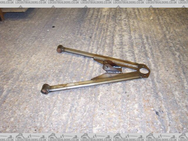
Taking a look at the photo at the top of this topic it looks very much like a classical buckle in the upper rear tube, which as described above is the
region of the structure carring the most compressive load, eureka. If its gonna buckle then it gonna be the top suface of the rear arm.
Add now BT 'scomments which are spot on. Where you have a weld the material has modified strength and stiffness properties, i.e potentially
degraded structural performance.
Where a structure is stiff, load will be attracted. for example a fatter plate welded onto the wishbone will "pickup" more load. This
presents a worse problem at the transition to the plain tube as you have more localised loading to distribute.
stress raisers!!!!
Hopefully this makes sense or ive just wasted alot of typing energy!!
Cheers Chaps.
C
p.s i didntmention that because of the offsets hand analysis may be inaccurate, fatigue of vibration..........
p.p.s I do know of people who have had issues of balljoints "bottoming out" and damaging wishbones, it was maily on the upper arm tho.
Have a look at the procomp locost racecar upper arm design and the LA Gold.
|
|
|