tilly819
|
| posted on 14/1/11 at 12:16 AM |

|
|
Upright Design Formula for applied forces ?????
Hi all
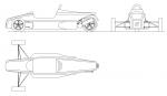
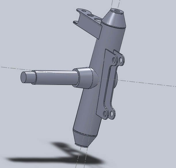
I am in the process of designing some front uprights and have been happily tapping away on CAD until i got to the FEA.
I am rather embarrassed to say that i have very little clue what figures in input? and what formula i need to use to calculate the correct forces?
so far i have established the flowing
car weight 600KG + 200 for 2 passengers
weight distribution 40F 60R
Max Cornering G 2 (in my dreams i think but it makes a nice ultimate figure)
for front suspension
for ease of maths im assuming 100% weight transfer to the outer wheels
fully loaded car in a 2G turn (2x 600) + (2 x200) = 1600Kg
front wheel load = 40% of 1600 = 640Kg
upper wishbone tensile force = 1/2 wheel load = 320Kg
Lower Wishbone Compressive force = 1.5 x wheel load = 960Kg
these are some formula that i have picked up from a couple off books and are very approximate i assume that the forces above (compressive and tensile)
will be the same forces the outer joints see????
however this confuses me also since the distances between the outer joints effects how much force they have fed into them this is what i relay could
do with begin able to calculate but have no idea were to begin.
also when i was modelling the part is FEA obviously the push and pull forces are applied to the upper and lower joint mounts but were do i apply my
clamp my first thought is to have it inside bearing housing on the central axis of the upright is this correct???
any formula for calculating the correct loads would be great and also any recommended reading on the subject would also be fantastic
apologies for the bombardment of questions but i feel this is something i cannot afford to get wrong!
thanks
tilly
Ps: this isnt for a 7 its for the *next car* Shhhh *wink*
|
|
|
|
|
Ivan
|
| posted on 14/1/11 at 07:07 AM |
|
|
Sorry to be a downer but for critical components FEA should be done by a qualified expert. Should not be expensive to pay a tame engineer to do it and
well worth the cost.
|
|
|
orton1966
|
| posted on 14/1/11 at 07:24 AM |
|
|
Also In Nottingham and working on uprights
As per title I am also in Nottingham and working on my own uprights, Id be really interested in comparing notes, I think it could be mutually
beneficial. I currently use Solidworks and have models for a fabricated tube based upright, also a model for a billet alloy one.
If you fancy sharing files or meeting up for a chat drop us a message
|
|
|
Ian-B
|
| posted on 14/1/11 at 07:32 AM |
|
|
I think you will struggle to get definitive answers and a single/few formulas to analyse an upright. As an upright will receive widely varying loads
in service, the most difficult aspect of the analysis is setting appropriate loading conditions. The first thing I would suggest is to discount the
rough loading guide for the suspension links you have quoted, if for no other reason than that to complete an analysis you first need to understand
the reasons behind the loads you are using as this will allow you to make sensible judgements on the analysis results.
I would recommend that you look at the most likely loading conditions braking, cornering and bump loads and likely the combination of these, this
needs to be considered with the intended use of the car, for example a race car is likely to receive a significant bump load whilst on limit cornering
where as a road the bump loads are unlikely to be combined with limit cornering. In considering your input loads you also need to establish your
design method, if you consider ultimate strength to be your liiting factor then it would be normal to select much higher abuse input loads, if you
believe fatigue is your limiting factor you would normally use the loads representing the higher end of the normal service loads, you may of course
choose both methods.
To understand how to calculate the input loads the first step is to create simple free body diagrams and resolve the forces, you should be able to
search for free body diagrams and the methods to resolve the forces if you are not familar.
Getting guidance from an engineer would be good advice, but if you have the right aptitude, are prepared to do your research and learn the methods
there is no reason you cannot complete the analysis you want.
Ian
|
|
|
designer
|
| posted on 14/1/11 at 08:57 AM |
|
|
The problem we amateurs have when designing something like this is that we tend to delve too deep.
FEA is banded about nowadays, and is OK when you are trying to make something as light as possible.
If your upright is made of decent materials and, above all, welded by a competent welder it will be OK.
|
|
|
orton1966
|
| posted on 14/1/11 at 10:17 AM |
|
|
Agreed
quote:
Originally posted by designer
The problem we amateurs have when designing something like this is that we tend to delve too deep.
FEA is banded about nowadays, and is OK when you are trying to make something as light as possible.
If your upright is made of decent materials and, above all, welded by a competent welder it will be OK.
Agreed
Also with something like solidworks you can make a reasonable stab at testing the design, even if you guess at the loads, overload it and it will tell
you where it will likely fail, you can then reassure yourself that that area is sufficiently over-engineered
|
|
|
v8kid
|
| posted on 14/1/11 at 10:34 AM |
|
|
Doing a few sums can help a lot though. Aurora publish a howto to article on estimating forces in upright rod ends. U2U me with your email for a
scan.
Also Stanniforth republished an article by Gould on contact patch forces with all the formulae and I put it on a spreadsheet if you are interested.
At the end of the day though, for the upright strength, you are going to assume the car is standing on one corner with all forces acting thro one
contact patch. 2G seems realistic to me for continuous loading but for shock loads it will be more. Dunno how much - 5G?
Realism also takes part and to weld easily with MIG you are looking at 1 to 2 mm which is more than strong enough.
Cheers
You'd be surprised how quickly the sales people at B&Q try and assist you after ignoring you for the past 15 minutes when you try and start a
chainsaw
|
|
|
Fred W B
|
| posted on 14/1/11 at 11:09 AM |
|
|
As above, the real engineering skill in FEA is deciding what load case to use.
In the real world safety critical steel fabrications that need to be optimised for mass (=material thickness) will be designed with an eye on the
desired fatigue life, not just the UTS.
Cheers
Fred W B
[Edited on 14/1/11 by Fred W B]
You can do it quickly. You can do it cheap. You can do it right. Pick any two.
|
|
|