hillbillyracer
|
| posted on 3/4/11 at 01:40 PM |

|
|
Speedo wiring, Pug 306 TD
The speedo has stopped on my parents' 306 turbo diesel (R reg, Phase 2), a word with the local Puggy specialist suggests the sensor on the diff
output is a fairly common fault & occasionally the clocks go wrong but that's it. I get a sensor from them & it does'nt fix it,
they kindly take it back & I go to the scrappy for a set of clocks. This does'nt fix it either!
So with my brother also has a 306TD so we try the bits on his car, I've got 2 sensors & a set of clocks from the scrappy plus the original
parts from the car & everything works fine on his car so this would seem to be a wiring issue & I buy a Haynes manual to get a circuit diagram
(could'nt find on on the tinternet).
The sensor has the live feed (but the voltage is lower than the battery has) & earth the diagram says it should have so I test for continuity
between the clocks & sensor & find non. But I do find as I test the other connections on the clock plugs incase I'd tried the wrong pin
& found the power from the multimeter would trip relays to put the rad fans in! Now my brother suggested could that be something to do with the
air-con, the thinking being here that when you switch the air-con on the fans come in but they wont be needed at speed so there could be some module
that reads the speedo signal & knocks them back off at say 25+mph? Anyway the air-con is stuffed so I could wire straight from the sensor to the
clocks right?
So I've got a section of wiring with each plug for the sensor & clocks when I was at the scrappy so I've wired the clocks up to a
battery & the sensor in to try & work them independantly from the car & I still can't get the bloody thing to work! If I flick the
senor signal wire at the clock the needle flicks around so I know the clocks are supplied with what they need, just not getting a signal.
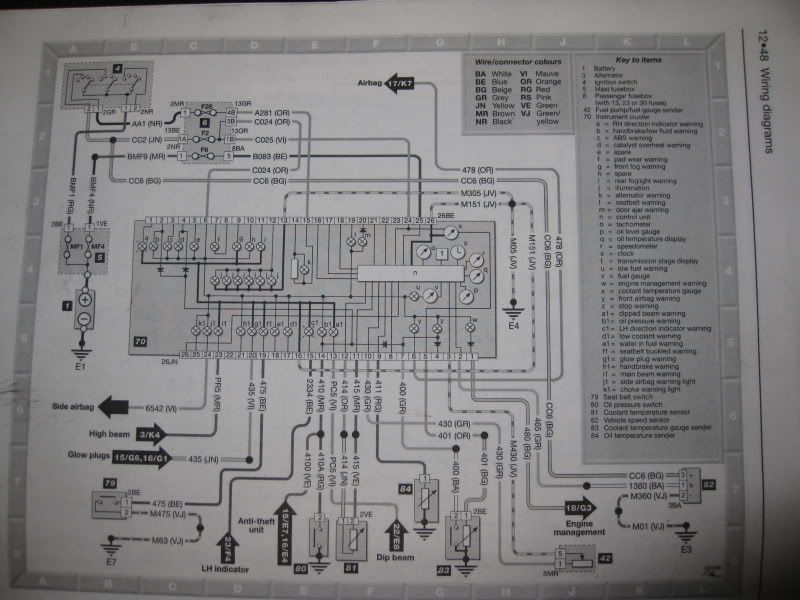
Here's the wiring diagrams for the clocks & sensor, can anyone see what I'm not seeing or know any quirks that Pug 306 speedos have?
As far as I see it the sensor gets a 12v feed & earth & one wire back to the clocks, & I've wired all the feeds & earths I can
see to the clocks. Could there be something missing from the diagram? It seems to be a generic 306 diagram rather than specific to the turbo
diesel.

|
|
|
|
|
hiflow
|
| posted on 3/4/11 at 02:52 PM |
|
|
Speedo
as you state you should have 12v supply , earth and the other pin in speed signal to dash. PM me tomorrow, when i,m at work and i,ll dig out the
wiring diag for you. Unbolt the O/s gearbox diff seal casing , 3x 13mm bolts (where the speed sensor plug into) you will need to remove the o/s
driveshaft. Inside this diff seal casing is a white plastic bevel gear that is driven off the driveshaft that drives the gear that turns speed
signal sensor, this gear tend to split and break, and therefore do not turn the speedo drive. Try this first.
Andy
hiflowheads.co.uk
|
|
|
hillbillyracer
|
| posted on 3/4/11 at 05:27 PM |
|
|
Well I've checked that the drive gear that goes up the inside of the sensor turns as the wheel goes round but that doesnt mean it's
turning properly once the sensor is in place, so the cracked plastic gear on the shaft output sounds plausable. But we've double checked this by
putting the gear (or at least the spare one from the scrappy) in a drill & working the sensor like that & it still did'nt work. We
tested the original sensor off the car & the scrappy one on my brother's car by plugging them in & using the drill on them, & my
drill does over 70mph!
A proper wiring diagram if one is available would be great, I was thinking of wiring it from scratch when it looks such a simple circuit to eleminate
the problem. Cheers for your help.
|
|
|
hillbillyracer
|
| posted on 24/4/11 at 02:36 PM |
|
|
This thing is still not fixed! Driving me nuts now!
There's a couple of boxes under the L/H headlight area that only air-con cars like this have & with the possible tie-in with the fans I
thought we'd try them & got a couple from the scrappy, no change though, still not working.
So I thought mabye when I tried running everything independantly with spare clocks etc on a battery mabye I'd missed some wire that was needed
so I've now wired a sensor to the clocks in the car & an independant live & earth to the sensor direct from the car's battery,
STILL NOTHING!! Again if I flick the sensor signal wire to earth (though I have it in my head the first time I did this it needed to flicked to a
live?) then the needle flicks around the dial & by doing it a lot the trip miles clocked 0.1 mile so it has to be a duff speed sensor right? But
when we tried both the spare ones from the scrappy on my brother's car turning them with a drill they work fine!
I've tried testing the sensors using this method here: http://www.youtube.com/watch?v=alR_toPdr4g but just get a steady voltage, sensor
turning or not but with them working on another car I'm thinking these sensors must work a different way to that?
|
|
|
hillbillyracer
|
| posted on 24/4/11 at 06:13 PM |
|
|
So nobody got any ideas? At least that means I've probably done all that most folk would have & I'm not missing something silly!
I do have access to a 13 ton tracked digger, could this possibly be used to help solve the problem?
|
|
|
DRC INDY 7
|
| posted on 24/4/11 at 06:30 PM |
|
|
The 3 wires 12v/ earth/ and signal wire have you check continuity ?
https://www.facebook.com/groups/462610273778799/
Puddle Dodgers Club
|
|
|
hillbillyracer
|
| posted on 24/4/11 at 06:41 PM |
|
|
Yeah, no probs with the live & earth, but testing between the dash & sensor plugs for continuity on the signal wire I did'nt have any,
but did find the power from the multi-meter would trip the relays to put the fans on! We were thinking that this was because the air-con puts the fans
on but once up to a decent speed it senses that through the speedo sensor & knocks them off.
Anyway, even with a sensor wired totally independant, live & earth direct to the battery & the signal wire run to the back of the clocks it
still doesnt work!
I'm thinking mabye I'll see if I can geta wiring diagram specifically for the car from a Peugeot dealer, if you can find the right man to
ask they can be very helpful (& very unhelpful if you get the wrong one!)
|
|
|
DRC INDY 7
|
| posted on 24/4/11 at 06:47 PM |
|
|
Well there is the problem no continuity on the signal wire which must have a break in line or short to earth
you seem to be getting confused you say the components work ok on another car but not on the original and that when wired independently still no joy
means its not wired correctly of the vehicle
[Edited on 4/24/2011 by DRC INDY 7]
https://www.facebook.com/groups/462610273778799/
Puddle Dodgers Club
|
|
|
hillbillyracer
|
| posted on 24/4/11 at 07:15 PM |
|
|
But I am wiring it as per the diagram above, which I'm questioning!
Surely it cant be that complicated, a live, an earth & a signal wire or is there more to it, is there something else between the snesor &
clocks not shown on the diagram I have?
|
|
|
DRC INDY 7
|
| posted on 24/4/11 at 07:21 PM |
|
|
You need continuity on the signal wire on the vehicle which you do not have so there lies a fault that needs to be corrected befroe anything else is
done plus power and earth which you say you have
https://www.facebook.com/groups/462610273778799/
Puddle Dodgers Club
|
|
|
hillbillyracer
|
| posted on 24/4/11 at 07:36 PM |
|
|
But, if I wire a speedo sensor up with a live from the car's battery, an earth to the car's battery, & run the signal wire to the
connection on the back of the clocks it should work should it not?
I was just going to run a new signal wire from the clocks down to the sensor but thought before I went to the hassle of running it through the
bulkhead etc, making a tidy job of it I'd wire the sensor seperately altogether just see that it was going to work & it doesnt. What reason
would there be that it wouldn't work like that?
|
|
|
hillbillyracer
|
| posted on 24/4/11 at 08:09 PM |
|
|
What I'm thinking here is if it doesnt work when wiring in indepentdantly with it all as the diagram in the first post I made here says it
should be is there something missing from the diagram that is fitted to this car? What should be different about wring it afresh as opposed to using
the car's original wiring if it's being supplied with all it needs according to the diagram?
When searching for info on the web about it I've found a 406 has an interface box in the speedo circuit, but could'nt find any reference
to it regarding a 306. Mabye phase 2 306's have one but it doesnt go wrong often & so no-one has posted any info on froums etc about?
|
|
|
DRC INDY 7
|
| posted on 24/4/11 at 08:09 PM |
|
|
You are making a simple job look very hard you have allready proved that the components works on youre brothers car so forget about off the car
wireing because its not working and just sort out the signal wire
https://www.facebook.com/groups/462610273778799/
Puddle Dodgers Club
|
|
|
hillbillyracer
|
| posted on 24/4/11 at 08:13 PM |
|
|
But if run a new signal wire from the sensor to the clocks then that IS sorting the the continuity problem! But it doesnt make the speedo work.
Anyway, thanks for your help, got to go now.
I'm trying to uderstand how it works so I can learn from it, if I've got a wiring diagram that's correct & all the relavent
components in good order then on or off the car it should work!
[Edited on 24/4/11 by hillbillyracer]
|
|
|


