beagley
|
| posted on 21/4/11 at 02:08 PM |

|
|
Anyone have hardships with designs in the head vs designs in CAD
I've been learning some new CAD software and I'm finding it rather difficult to take the view I have in my head and put it into the CAD
system. I'm looking at my chassis that I'm working on thinking I just need a simple piece from here to there. Not a big deal, but I am
having a horrendous time trying to get the tubing lined up correctly.
Is this a new problem or has it been around awhile and I'm just discovering it?
Beags
I'm not scared!!! I'm just marking my territory.
|
|
|
|
|
Mr Whippy
|
| posted on 21/4/11 at 02:24 PM |
|
|
With cad you do have to pay close attention to decimal places. For example an angle, you may have it displayed as say 55 degs due to how many decimal
places you have selected to show for the dimensions, in fact it is in reality 54.6 deg or even 54.56 and so on, it will never line up without double
checking what's after the decimal place. This is something I learned early on with AutoCAD, especially with angles.
One way round this is to use the snap to function as that gets round this problem by doing the work for you but I found that space frames in AutoCAD
and other programs were a ball braking task tbh, they can be done but make sure you have all the horizontal and vertical structure totally correct
before going on to the bracing otherwise corrections will need a lot of reworking.
Even when using cad it is good practice to do some hand drawn isometric type sketches before putting it to cad as you will have a better idea of how
things will fit together. When ever I do designs for houses, model planes, cars etc 90% of my time is just doing doodles and sketches
[Edited on 21/4/11 by Mr Whippy]
Fame is when your old car is plastered all over the internet
|
|
|
beagley
|
| posted on 21/4/11 at 02:35 PM |
|
|
quote:
Originally posted by Mr Whippy
With cad you do have to pay close attention to decimal places.
You're preaching to the choir with that statement. I write computer software for a living, specifically inventory management. We do all sorts
of unit conversions with different products and learned the hard way about decimal precision. I've since been "upgraded" to
conversion guru at the office.
For the most part I'm able to get things drawn in CAD quickly and easily, but recently there seem to be a couple of specific beams that I
can't quite draw correctly.
It could be that the drawings I'm working from don't have all of the measurements so I'm having to calculate what they need to be.
Oh well, seems I have plenty of time to putz around with this stuff.
Beags
I'm not scared!!! I'm just marking my territory.
|
|
|
Mr Whippy
|
| posted on 21/4/11 at 02:40 PM |
|
|
post some screen dumps on here so we can see the issue. I'm just not sure what you are having a problem with tbh there are many sticking points
with cad
Fame is when your old car is plastered all over the internet
|
|
|
beagley
|
| posted on 21/4/11 at 02:50 PM |
|
|
Well, here is one of the places I'm getting bogged down with.
There is a cross member that follows the path of the Red line in the below picture. It connects to the bottom face of the top rail where the angled
bar meets the side rail.
 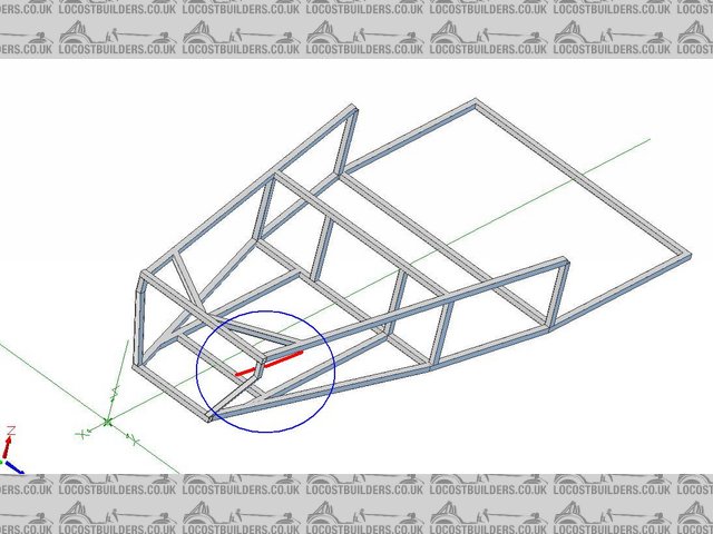
Cross Member Problem
With the way that I have been using sweep bosses to create the square tubing this piece is more difficult because neither end of the tube is square to
either piece it is to be welded to. I'll get there eventually, I was just wondering if tubing was this much of a problem with any other CAD
software.
Beags
I'm not scared!!! I'm just marking my territory.
|
|
|
Miks15
|
| posted on 21/4/11 at 03:01 PM |
|
|
what i would do there is make an over size bar of the right size etc.
Then on the surface of the part do two cuts, one for each end of the bar with the right dimensions
Or do a swept cut using the angles and everything of the existing bars
|
|
|
Mr Whippy
|
| posted on 21/4/11 at 03:14 PM |
|
|
yeah I can see why your having issues with that one!
My solution would be to work from the tubes centre line on the uppermost surface, ignoring at first the width of the tube just draw a line. Then
project 90 degs from either side the midpoint of the line to create a flat plane perpendicular to the line that represents the cross section of the
tube. Then either copy that cross section to either end of the initial line and joint up the corners or extrude the surface if the software will do
that. Hope that makes sense  it's easy but you need to get your head around having to make the construction lines first then use them to
create a tube. it's easy but you need to get your head around having to make the construction lines first then use them to
create a tube.
Fame is when your old car is plastered all over the internet
|
|
|
beagley
|
| posted on 21/4/11 at 03:21 PM |
|
|
Thats what I will be attempting here in a few minutes. I tried to do that yesterday and I think I almost had it, but got frustrated since it was the
last piece I was trying to finish before getting back to work. Thanks for the input guys, hopefully I will have some new photos to upload today.

Beags
I'm not scared!!! I'm just marking my territory.
|
|
|
Mr Whippy
|
| posted on 21/4/11 at 03:24 PM |
|
|
here's a step by step picture to go along with my ramblings...hope it helps

Fame is when your old car is plastered all over the internet
|
|
|
Doctor Derek Doctors
|
| posted on 21/4/11 at 05:01 PM |
|
|
Everyone struggles with CAD to start with, its the design intent that takes a while to learn as often CAD doesn't model things how they are
made.
I.E to make that tube, you would cut a piece, shape the ends and the put it were it needs to be. In CAD world though you decide on a profile, then
where it will go and finally tell it were to start and stop.
Personally to make that tube I would add two points on the tubes to go between were the centre of the tube you are making is to go to. Then add a 3D
line between those two points, then a 'Point-Direction' plane in the middle of that line and on that plane draw the tube profile. Then
extrude the profile in both directions 'Up to next' so it just extrudes both ways until it meets the other tubes.
The problem is thats how I'd do it in CATIA, I wouldn't do it like that in NX or SolidWorks.
As a piece of general advice for designing a tube chassis, use 3D points connected with 3D lines to design the chassis tube positions, add Planes for
the bilkheads and make sure that 0,0,0 is in the middle of the front axle centreline. Do this for all of the tubes so you have a complete wireframe of
the chassis as a Geometry set. Then when that is FINISHED start using that wireframe to add solid tube models.
If you just start modelling tubes you'll end up in a right mess.
Does the CAD system you are using not have a 'tube' button?
|
NOTE:This user is registered as a LocostBuilders trader and may offer commercial services to other users
|
beagley
|
| posted on 21/4/11 at 05:08 PM |
|
|
quote:
Originally posted by Doctor Derek Doctors
Does the CAD system you are using not have a 'tube' button?
Not that I have seen. I've been through the tutorials and really been trying to learn this stuff. I've been going through and drawing
the 3d lines and then extruding the shape along that path. With Alibre I can't have branches in the 3d path which makes the chassis much more
difficult. If I could just draw the cage a series of 3d points and then press the magic "tube" button I would have been done a LONG time
ago. On the other hand I have really learned alot about working in different planes and just getting better at drawing in 3d.
BUT.... in an AMAZINGLY pin headed move I just now remembered that there is an appendix in the rear of the book that gives the actual dimensions of
every piece used in the book.   Where's the emberrassed smiley face? Where's the emberrassed smiley face?
Beags
I'm not scared!!! I'm just marking my territory.
|
|
|
Doctor Derek Doctors
|
| posted on 21/4/11 at 05:20 PM |
|
|
Are you using a single body full of pads and extrudes or are you using Boolean operations?
|
NOTE:This user is registered as a LocostBuilders trader and may offer commercial services to other users
|
beagley
|
| posted on 21/4/11 at 05:30 PM |
|
|
I haven't yet learned about boolean operations. Alibre is capable of it but haven't known that I've needed them yet.
I really feel like an @rse for not remembering the appendix..... guess it will have to wait till tomorrow. Unless I shirk off my work duties today
and continue to play.
Decisions descisions...
Thanks for all the input guys!
I'm not scared!!! I'm just marking my territory.
|
|
|
Ian-B
|
| posted on 21/4/11 at 05:58 PM |
|
|
I use Alibre for my car design, the method I have used is to design in the assembly environment, with each tube being a seperate part. I start by
defining my chassis in a an assembly by constructing points and axes, for the nodes and tube runs respectively, and planes to allow tube orientaintion
to be set.
Then insert the simple straight cut tubes using the assembly constaints tools (align and mate). For tubes with mitred ends I insert and constain an
over long tube, once I am happy with the position (easy to adjust by moving the node points), I anchor the part and remove the constraints, then edit
the tube in the current assembly, create a plane from the intersecting tube, sketch on this plane a suitable shape to cut the end of the tube and use
the extrude cut to trim the tubes.
Once complete return to edit the route assembly and remove interdesign constriants.
The reason for anchoring parts rather than leaving the assembly constraints in place is that this provides a more stable model, Alibre can be a little
unpredictable when constraining to axes and points.
The reason for removing interdesign constraints is again to ensure a stable model.
This method may not be the best method, but has worked well for my needs (requiring each tube to be an individual part). I think you may struggle with
more complex tube joins when trying to model all tubes in one part in Alibre.
Ian
|
|
|
beagley
|
| posted on 21/4/11 at 07:03 PM |
|
|
quote:
Originally posted by Ian-B
I use Alibre for my car design, the method I have used is to design in the assembly environment, with each tube being a seperate part. I start by
defining my chassis in a an assembly by constructing points and axes, for the nodes and tube runs respectively, and planes to allow tube orientaintion
to be set.
Then insert the simple straight cut tubes using the assembly constaints tools (align and mate). For tubes with mitred ends I insert and constain an
over long tube, once I am happy with the position (easy to adjust by moving the node points), I anchor the part and remove the constraints, then edit
the tube in the current assembly, create a plane from the intersecting tube, sketch on this plane a suitable shape to cut the end of the tube and use
the extrude cut to trim the tubes.
Once complete return to edit the route assembly and remove interdesign constriants.
The reason for anchoring parts rather than leaving the assembly constraints in place is that this provides a more stable model, Alibre can be a little
unpredictable when constraining to axes and points.
The reason for removing interdesign constraints is again to ensure a stable model.
This method may not be the best method, but has worked well for my needs (requiring each tube to be an individual part). I think you may struggle with
more complex tube joins when trying to model all tubes in one part in Alibre.
Ian
That totally makes sense. It sounds like I'm taking the long way around to develop a chassis then. I will give your method a try this coming
week.
I'm not scared!!! I'm just marking my territory.
|
|
|